Table of Contents
Advertisement
Available languages
Available languages
Quick Links
Download this manual
See also:
Operating Manual
Bedienungsanleitung
D
BENNING ST 710 mit Schweizer Steckersystem und
Firmware, Art.-Nr. 050315
Operating manual
BENNING ST 710 with Swiss plug system and
firmware, item no. 050315
Notice d'emploi
F
BENNING ST 710 avec système de connecteurs et
micrologiciel suisses, réf. 050315
Istruzioni d'uso
I
BENNING ST 710 con sistema di spina svizzero e
firmware, n. 050315
R
PE
R
ISO
ON/OFF
press 2 sec.
Klasse I
Klasse II
Class I
Class II
R
PE
R
R
ISO
ISO
I
I
EA
EA
DIN VDE 0701-0702, DGUV V3, ÖVE / ÖNORM E 8701, NEN 3140
Prüfling während der Prüfung einschalten
Switch on test object during test
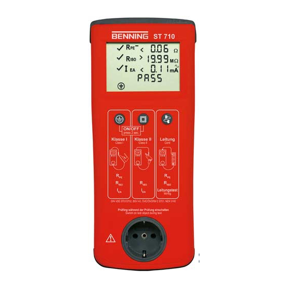
ST 710
M
A
m
Leitung
Cord
R
PE
R
ISO
Leitungstest
Wiring
Advertisement
Chapters
Table of Contents

Subscribe to Our Youtube Channel
Related Manuals for Benning ST 710


Summary of Contents for Benning ST 710
- Page 1 050315 Notice d’emploi BENNING ST 710 avec système de connecteurs et micrologiciel suisses, réf. 050315 Istruzioni d’uso BENNING ST 710 con sistema di spina svizzero e firmware, n. 050315 ST 710 ON/OFF press 2 sec. Klasse I...
- Page 2 Figura 2: Lato superiore strumento Fig. 2: Top side of the device Fig. 2: Bovenaanzicht apparaat Fig. 2: Face supérieure de l'appareil Rys. 2: Górna strona urządzenia Obr. 2: Horní strana přístroje Bild 2: Ovansida BENNING ST 710 07/ 2018...
- Page 3 III klasy ochronnej (małe napięcie ochronne) Bild 4: Test av utrustning med skyddsklass II (skyddsisolerad utrustning utan skyddsledare och med åtkomstbara ledande delar) resp. test av utrustning med skyddsklass III (skyddsklenspänning) BENNING ST 710 07/ 2018...
- Page 4 Klasse I Klasse II Leitung Class I Class II Cord Leitungstest Wiring DIN VDE 0701-0702, DGUV V3, ÖVE / ÖNORM E 8701, NEN 3140 Prüfling während der Prüfung einschalten Switch on test object during test BENNING ST 710 07/ 2018...
- Page 5 Switch on test object during test Bild 7: Batteriewechsel Fig. 7: Battery replacement Fig. 7: Remplacement des piles Obr. 7: Výměna baterií Figura 7: Sostituzione batterie Fig. 7: Vervanging van de batterij. Rys. 7: Wymiana baterii Bild 7: Batteribyte BENNING ST 710 07/ 2018...
-
Page 6: Table Of Contents
Elektrofachkräfte (EF), befähigte Personen und Elektrotechnisch unterwiesene Personen (EuP) Das BENNING ST 710 ist zur Messung in trockener Umgebung vorgesehen. Es darf nicht in Stromkreisen mit einer höheren Nennspannung als 300 V AC eingesetzt werden (näheres hierzu im Abschnitt 6: Umgebungsbedingungen). -
Page 7: Sicherheitshinweise
Extreme Vorsicht bei Arbeiten um blanke Leiter oder Hauptleitungsträger. Ein Kontakt mit Leitern kann einen Elektroschock verursachen. Das BENNING ST 710 darf nur in Stromkreisen der Überspannungskategorie II mit max. 300 V Leiter gegen Erde benutzt werden. Beachten Sie, dass Arbeiten an spannungsführenden Teilen und Anlagen grundsätzlich gefährlich sind. -
Page 8: Gerätebeschreibung
Das BENNING ST 710 führt elektrische Sicherheitsüberprüfungen nach DIN VDE 0701-0702, BGV A3, ÖVE/ ÖNORM E8701 und NEN 3140 aus. Eigenständig überprüft das BENNING ST 710 die Art des angeschlossenen Prüfobjekts und gibt den Benutzer einen Hinweis bei unkorrekter Auswahl der Prüfablaufs [ 2 ... 4 ]: Voreingestellte Grenzwerte und Messergebnisse mit gut/ schlecht Aussage erleichtern die Bewertung der Prüfung. -
Page 9: Prüfen Mit Dem Benning St 710
PE-Verbindung Prüfen mit dem BENNING ST 710 8.1 Vorbereiten der Prüfung Benutzen und lagern Sie das BENNING ST 710 nur bei den angegebenen Lager- und Arbeits- temperaturbedingungen, vermeiden Sie dauernde Sonneneinstrahlung. Angaben von Nennspannung und Nennstrom auf den Sicherheitsmessleitungen überprü- fen. - Page 10 8.1.1 Ein-, Ausschalten des BENNING ST 710 Durch ein gedrückt halten der Tasten 2 + 3 für ca. 3 Sekunden wird das BENNING ST 710 ein- geschaltet, 2 Signaltöne bestätigen dies. Erneutes drücken der Tasten schaltet das Gerät aus. Das BENNING ST 710 schaltet sich nach ca. 3 Minuten selbstständig ab. (APO, Auto-Power- Off).
- Page 11 Sek. bis das Symbol im Display erscheint. Bewegen Sie die Anschlussleitung des Prüfobjektes über die komplette Länge um eine Schwachstelle oder einen Bruch in der Schutzleiterbahn festzustellen. Das BENNING ST 710 erfasst fortlaufend den aktuel- len Messwert im Display und hinterlegt den Maximalwert im Speicher. Durch erneuten Druck auf die Taste 2 wird die Messung mit vertauschter Polarität durchgeführt.
- Page 12 Schutzklasse III (Schutzkleinspannung) Prüfung von Geräten ohne Schutzleiter und mit berührbaren leitfähigen Teilen. Das Prüfobjekt muss an die Prüfsteckdose 1 des BENNING ST 710 angeschlossen werden. Stellen Sie eine Verbindung zwischen der 4 mm Prüfbuchse 6 und einem Metallteil des Prüfobjekts mittels der Prüfleitung mit Abgreifklemme her.
- Page 13 Sek. bis das Symbol im Display erscheint. Bewegen Sie die Anschlussleitung des Prüfobjektes über die komplette Länge um eine Schwachstelle oder einen Bruch in der Schutzleiterbahn festzustellen. Das BENNING ST 710 erfasst fortlaufend den aktuel- len Messwert im Display und hinterlegt den Maximalwert im Speicher. Durch erneuten Druck auf die Taste 4 wird die Messung mit vertauschter Polarität durchgeführt.
-
Page 14: Instandhaltung
So wechseln Sie die Batterie (siehe Bild 7): Schalten Sie das BENNING ST 710 aus. Legen Sie das BENNING ST 710 auf die Frontseite und lösen Sie die Schraube vom Bat- teriedeckel. Heben Sie den Batteriedeckel (im Bereich der Gehäusevertiefungen) vom Unterteil ab. -
Page 15: Umweltschutz
9.4 Kalibrierung BENNING garantiert die Einhaltung der in der Bedienungsanleitung aufgeführten technischen Spezifikationen und Genauigkeitsangaben für das erste Jahr nach dem Auslieferungsdatum. Um die angegebenen Genauigkeiten der Messergebnisse zu erhalten, muss das Gerät regelmäßig durch unseren Werksservice kalibriert werden. Wir empfehlen ein Kalibrierintervall von einem Jahr. Senden Sie hierzu das Gerät an folgende Adresse: Benning Elektrotechnik &... -
Page 16: User Notes
The BENNING ST 710 is intended for making measurements in dry environment. It must not be used in power circuits with a nominal voltage higher than 300 V AC (More details in Section 6. “Ambient conditions”). -
Page 17: Safety Note
3.5 Six 1.5-V-batteries/ type AA (IEC LR6) fitted in the unit as initial equipment, 3.4 One operating manual Parts subject to wear: The BENNING ST 710 is supplied by six 1.5 V batteries/ type AA (IEC LR6). Note on optional accessories: Test badges “next test date”, 300 pieces... -
Page 18: Unit Description
6 4 mm test socket, for connecting the test lead with alligator clip 7 IEC connector, for connecting the IEC power cord General information The BENNING ST 710 is intended for electrical safety tests according to DIN VDE 0701-0702, BGV A3, ÖVE/ ÖNORM E8701 and NEN 3140. Automatically, the BENNING ST 710 verifies the type of the connected test object and informs the user in case of incorrect selection of the testing procedure [ 2 ... -
Page 19: Measuring With The Benning St 710
Do not permanently expose the device to sunlight. Check rated voltage and rated current details specified on the safety measuring leads. Strong sources of interference in the vicinity of the BENNING ST 710 might lead to unstable readings and measuring errors. - Page 20 Switching the BENNING ST 710 ON/ OFF Press and hold the keys 2 and 3 for approx. 3 seconds to switch the BENNING ST 710 on. 2 acoustic signals confirm that the device is switched on. Press the keys again to switch the device off.
- Page 21 The BENNING ST 710 continuously records the current measured value on the display and stores the maximum value in the memory. By pressing the key 2 again, the measurement is carried out with reversed polarity.
- Page 22 IEC coupler) and for the testing of cable reels, multiple distributors and extension cables. 8.2.3.1 Testing of IEC power cords (IEC adapter cables) Connect the IEC power cord to be tested to the BENNING ST 710 by means of the IEC con- nector 7 and the test socket 1 .
- Page 23 The BENNING ST 710 continuously records the current measured value on the display and stores the maximum value in the memory. By pressing the key 4 again, the measurement is carried out with reversed polarity.
- Page 24 Work on the opened BENNING ST 710 under voltage must be carried out by skilled electri- cians with special precautions for the prevention of accidents only. Make sure that the BENNING ST 710 is free of voltage as described below before opening the instrument: Switch the tester off.
- Page 25 Please inform yourself in your community. 9.4 Calibration Benning guarantees compliance with the technical and accuracy specifications stated in the operating manual for the first 12 months after the delivery date. To maintain the specified preci- sion of the measurement results, the instrument must be recalibrated at regular intervals by our factory service.
- Page 26 électrotechnique Le BENNING ST 710 est conçu pour effectuer des mesures dans un environnement sec. Il ne doit pas être utilisé dans des circuits dont la tension nominale est supérieure à 300 V CA (pour de plus amples informations, consulter la section «...
-
Page 27: Consignes De Sécurité
3.5 six piles rondes de 1,5 V mignon (IEC LR 6/ AA) montées initialement dans l’appareil, 3.6 une notice d’emploi. Remarque concernant les pièces d’usure : Le BENNING ST 710 est alimenté par six piles rondes incorporées de 1,5 V mignon (IEC LR6/ AA). Remarque concernant les accessoires en option : plaquettes d'essai «... -
Page 28: Description De L'appareil
7 fiche mâle CEI (connecteur CEI), afin de raccorder le câble d'alimentation CEI Indications générales Le contrôleur BENNING ST 710 sert à effectuer des contrôles de sécurité conformément à DIN VDE 0701-0702, BGV A3, ÖVE/ ÖNORM E8701 et NEN 3140. - Page 29 - tension entre le conducteur neutre (N) et le conducteur de terre (PE) 7.6 Valeurs limites selon DIN VDE 0701-0702 et ÖVE/ ÖNORM E 8701-1 Remarque: Les valeurs limites préréglées imprimées en gras sont mémorisées dans l'appareil BENNING ST 710. Classe de protection I Classe de...
-
Page 30: Mesure Avec Le Benning St 710
8.1.1 Mise en marche/ en arrêt du contrôleur BENNING ST 710 L'appareil BENNING ST 710 est allumé en maintenant appuyées les touches 2 et 3 pour 3 secondes environ. La mise en marche est confirmée par 2 signaux acoustiques. Appuyez sur les touches encore une fois afin d'éteindre l'appareil. Après 3 minutes environ, l'appareil BENNING ST 710 s'éteint automatiquement (APO, Auto- Power-Off). - Page 31 à côté du symbole I , si le courant du conducteur de protection I est inférieur à la valeur limite admissible. Le contrôle est considéré comme réussi, si le symbole « PASS » est affiché sur l'écran. BENNING ST 710 07/ 2018...
- Page 32 Contrôle des appareils sans conducteur de protection et avec des pièces touchables conductrices Raccordez l'objet de contrôle à la prise de test 1 du contrôleur BENNING ST 710. Établissez une connexion entre la douille de test 4 mm 6 et une pièce métallique de l'objet de contrôle au moyen du câble d'essai avec pince crocodile.
- Page 33 8.2.3.1 Contrôle de câbles d'alimentation CEI ( câble d'adaptateur CEI ) Connectez le câble d'alimentation CEI à contrôler à l'appareil BENNING ST 710 au moyen de la fiche mâle CEI 7 et la prise de test 1 . Appuyez sur la touche 4 afin de commencer le contrôle automatique.
-
Page 34: Entretien
Dans ces cas, il faut mettre le BENNING ST 710 immédiatement hors circuit, le retirer du point de mesure et le protéger de manière à ne plus être utilisé. -
Page 35: Information Sur L'environnement
Remplacez les piles de la manière suivante: Éteignez l'appareil BENNING ST 710. Posez l'appareil BENNING ST 710 sur la face avant et dévissez la vis du couvercle du compartiment à piles. Soulevez le couvercle du compartiment à piles (au niveau des cavités du boîtier) de la partie inférieure de l'appareil. - Page 36 (EF), persone capaci e - personale qualificato in elettrotecnica (EuP) Lo strumento BENNING ST 710 è previsto per effettuare misurazioni in ambienti asciutti. Non può essere utilizzato in circuiti con tensione nominale superiore a 300 V CA (per dettagli vedere la Sezione 6: condizioni ambientali).
- Page 37 Accoppiamento 32 A CEE - spina con contatto di terra 16 A (044123) in alternativa: Pinza corrente di dispersione BENNING CM 9 per misurare la corrente differenziale, la cor- rente del conduttore di protezione e la corrente di carico per utenti alimentazione uno e...
- Page 38 6 4 mm Presa di prova, per collegare una linea di prova con morsetto 7 Connettore IEC (spina-IEC), per collegare il cavo di alimentazione Dati di carattere generale BENNING ST 710 esegue test per la sicurezza elettrica conformemente a DIN VDE 0701-0702, BGV A3 e ÖVE/ ÖNORM E8701. BENNING ST 710 verifica automaticamente il tipo di oggetto di test da collegare ed informa l’u- tente della scelta scorretta della procedura di prova [ 2 ...
- Page 39 PE Test con BENNING ST 710 8.1 Preparazione dei test Utilizzare ed immagazzinare BENNING ST 710 solo nelle condizioni di temperatura di lavoro e di immagazzinamento specificate, evitare l’esposizione prolungata alla luce solare. Controllare la tensione nominale e la corrente nominale specificate sui cavi di misurazione di sicurezza.
- Page 40 8.1.1 Accensione - spegnimento di BENNING ST 710 Tenendo premuti i tasti 2 + 3 per circa 3 secondi, BENNING ST 710 viene acceso, 2 segnali acustici lo confermano. Premendo nuovamente il tasto, il dispositivo si spegne. BENNING ST 710 si spegne dopo circa 3 minuti. (APO, Auto-Power-Off). Si riaccende quando vengono premuti i tasti 2 + 3 .
- Page 41 BENNING ST 710 legge continuamente sul display il valore di misurazione attuale e memorizza il valore massimo. Premendo di nuovo sul tasto 2 la misurazione viene effettuata con la polarità...
- Page 42 Controllo di dispositivi senza conduttore di protezione e con parti conduttrici esposte. L’oggetto di prova deve essere collegato alla presa di prova 1 di BENNING ST 710. Creare una connessione fra la presa di prova 6 da 4 mm ed una parte metallica dell’oggetto di prova per mezzo del cavo di prova con morsetto a pinza.
- Page 43 8.3 Misura della tensione sulla presa con contatto di terra esterna Collegare la linea IEC (cavi adattatori IEC) sul connettore IEC 7 di BENNING ST 710. Collegare la spina con contatto di terra alla presa con contatto di terra da controllare. Con una tensione di rete applicata viene avviata automaticamente la misurazione della tensione.
- Page 44 Qualsiasi lavoro su BENNING ST 710 una volta aperto e sotto tensione deve essere effettuato solo da elettricisti esperti, che possono adottare misure per prevenire incidenti. Accertarsi che BENNING ST 710 non sia sotto tensione come descritto prima di aprire lo strumento: Spegnere il tester Staccare tutti i cavi di connessione dallo strumento 9.1 Messa in sicurezza dello strumento...
- Page 45 10. Tutela ambientale Una volta terminata la vita utile dello strumento, smaltirlo presso i punti di raccolta specifici per questo tipo di rifiuti. BENNING ST 710 07/ 2018...
- Page 46 Benning Elektrotechnik & Elektronik GmbH & Co. KG Münsterstraße 135 - 137 D - 46397 Bocholt Phone: +49 (0) 2871 - 93 - 0 • Fax: +49 (0) 2871 - 93 - 429 www.benning.de • E-Mail: duspol@benning.de...
Need help?
Do you have a question about the ST 710 and is the answer not in the manual?
Questions and answers