Sign In
Upload
Manuals
Brands
LS Industrial Systems Manuals
Controller
MASTER-K80S
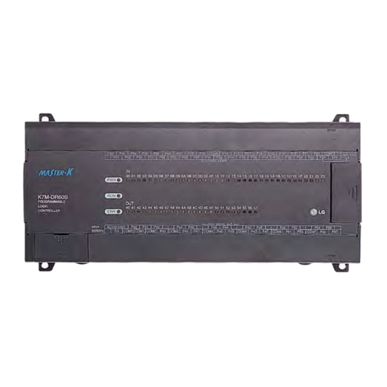
LS Industrial Systems MASTER-K80S Manuals
Manuals and User Guides for LS Industrial Systems MASTER-K80S. We have
1
LS Industrial Systems MASTER-K80S manual available for free PDF download: User Manual
LS Industrial Systems MASTER-K80S User Manual (252 pages)
LS Programmable Logic Controller
Brand:
LS Industrial Systems
| Category:
Controller
| Size: 2 MB
Table of Contents
Safety Instructions
2
Design Precautions
3
Installation Precautions
4
Wiring Precautions
5
Startup and Maintenance Precautions
6
Table of Contents
7
How to Use this Manual
12
Chapter 1 . General∙∙∙∙∙∙∙∙∙∙∙∙∙∙∙∙∙∙∙∙∙∙∙∙∙∙∙∙∙∙∙∙∙∙∙∙∙∙∙∙∙∙∙∙∙∙∙∙∙∙∙∙∙∙∙∙∙∙∙∙∙∙∙∙∙∙∙∙∙∙∙∙∙∙∙∙∙∙∙∙∙∙∙∙∙∙∙∙∙∙∙∙∙ 1-1~1-6
13
Features
13
Terminology
15
Chapter 2. System Configuration
17
Overall Configuration
17
Basic System
17
Cnet I/F System
18
Communications System
18
Product Functional Model
20
Product Function Block
20
System Equipment
21
General Specifications
23
Chapter 3. GENERAL SPECIFICATION
23
Names of Parts
24
Base Unit View
24
Chapter 4. Names of
24
10-Point Base Unit
26
20-Point Base Unit
26
30-Points Base Unit
27
40-Points Base Unit
27
60-Points Base Unit
27
Expansion Module
28
Digital I/O Module
28
A/D .... D/A Combination Module
28
Analog Timer Module
28
Option Modules
29
CPU Specifications
30
Chapter 5. CPU
30
Operation Processing
32
Method
32
CPU Part
32
Operation Processing at Momentary Power Failure Occurrence
33
Scan Time
34
Scan-Watchdog Timer
34
Timer Processing
35
Counter Processing
38
Classification of Program
40
Processing Method
40
Program Configuration
40
Interrupt Function
41
Process Driven Interrupt
42
Error Handling
43
Error Classification
43
Operation Mode at Error Occurrence
43
Operation Modes
44
RUN Mode
44
Processing When the Operation Mode Changes
44
Operation Processing Contents
44
STOP Mode
45
PAUSE Mode
45
DEBUG Mode
45
Operation Mode Change
46
Remote Operation Mode Change
47
Remote Operation Mode Change Enable/Disable
47
Functions
48
Self-Diagnosis
48
I/O Force On/Off Function
49
Special Data Register for Forced I/O Set
51
Force On/ off Processing Timing and Method
51
Direct I/O Operation Function
52
System Error History
52
Memory Configuration
53
I/O No. Allocation Method
54
Built-In Flash Memory
55
Structure
55
Usage
56
External Memory Module
58
Structure
58
Usage
58
RTC Module
60
Structure
60
Usage
60
Battery Specifications
62
Battery Replacement
62
Chapter 6 Input and Output Modules
63
Input and Output Specifications
63
Base Unit
64
Digital Input Specification
64
Example of External Devices
68
Expansion Module Specifications
69
Base Unit (Relay Output)
70
Digital Output Specification
70
Base Unit (Transistor Output) Specifications
74
Module
77
Built-In Functions
78
High-Speed Counter Function
78
Usage of Various Functions
78
Chapter 7. Usage of Various 7-1~7-60
78
Pulse Output Function
88
Pulse Output
90
Function
96
Pulse Catch Function
100
Input Filter Function
102
PID Control Function
103
The Block Diagram of Anti-Windup Control System
112
The PV Output Characteristics with Different Tt Values
112
Realization of PID Control on the PLC
112
External Interrupt Function
125
Special Module
127
A/D·D/A Combination Module
127
Scaling Function
130
I/O Converstion Characteristics
132
A/D Conversion Module Performance Specifications
136
Analog/Digital Conversion Characteristics
140
Distinction Program of A/D Conversion Value
141
Analog Timer
142
Reading A/T Conversion Value
143
Dedicated Protocol Communication
144
Chapter 8 Communication Function
144
Introduction
144
System Configuration Method
145
Frame Structure
148
List of Commands
150
Execution of
150
Data Type
151
Execution of Commands
152
1:1 Built-In Communication between Units
172
Error Code
185
User Defined Protocol Communication
187
Introduction
187
Parameter Setting
188
Setting Communications Parameter
188
Instruction
197
Function
197
Example of Use
198
Modbus Protocol Communication
208
Introduction
208
Function
208
Installation and Wiring
218
Installation Environment
218
Chapter 9. Installation and Wiring ∙∙∙∙∙∙∙∙∙∙∙∙∙∙∙∙∙∙∙∙∙∙∙∙∙∙∙∙∙∙∙∙∙∙∙∙∙∙∙∙∙∙∙∙∙∙∙∙∙∙∙∙∙∙∙∙∙∙∙∙∙∙∙∙∙∙∙∙∙∙9-1~9-11
218
Handling Instructions
221
Mounting Instructions
222
Connection of Expansion Module
224
Power Supply Wiring
225
Input and Output Devices Wiring
227
Grounding
227
Cable Specifications for Wiring
228
Chapter 10 . Maintenance∙∙∙∙∙∙∙∙∙∙∙∙∙∙∙∙∙∙∙∙∙∙∙∙∙∙∙∙∙∙∙∙∙∙∙∙∙∙∙∙∙∙∙∙∙∙∙∙∙∙∙∙∙∙∙∙∙∙∙∙∙∙∙∙∙∙∙∙∙∙∙∙∙∙∙∙∙ 10-1~10-2
229
Maintenance and Inspection
229
Daily Inspection
229
Periodic Inspection
230
Chapter 11 Troubleshooting
231
Basic Procedures of Troubleshooting
231
Troubleshooting Flowchart Used When the POWER LED Turns off
232
Troubleshooting Flowchart Used When the ERR LED Is Flickering
233
Troubleshooting Flowchart Used When the RUN Turns off
234
Troubleshooting Flowchart - When I/O Part Doesn’t Operate Normally
235
Troubleshooting - When a Program Cannot be Written to the CPU
237
Troubleshooting Questionnaire
238
Troubleshooting Examples
239
Input Circuit Troubles and Corrective Actions
239
Output Circuit Troubles and Corrective Actions
240
Error Code List
242
System Definitions
244
Flag List
248
External Dimensions
251
Advertisement
Advertisement
Related Products
LS Industrial Systems Metasol Series
LS Industrial Systems MB-2000
LS Industrial Systems G0L-GWRA
LS Industrial Systems G3L-RUEA
LS Industrial Systems G3L-RUREA
LS Industrial Systems G4L-RUEA
LS Industrial Systems G4L-RUREA
LS Industrial Systems G6L-RUEA
LS Industrial Systems G6L-RUREA
LS Industrial Systems G7L-RUEA
LS Industrial Systems Categories
Controller
Inverter
Control Unit
DC Drives
Circuit breakers
More LS Industrial Systems Manuals
Login
Sign In
OR
Sign in with Facebook
Sign in with Google
Upload manual
Upload from disk
Upload from URL