Festo SPC200 Manual
Positioning system, smart positioning controller
Hide thumbs
Also See for SPC200:
- System manual (506 pages) ,
- Manual (404 pages) ,
- Electronic manual (103 pages)
Table of Contents
Advertisement
Quick Links
Advertisement
Table of Contents

Related Manuals for Festo SPC200


Summary of Contents for Festo SPC200
- Page 1 Positioning system Smart Positioning Controller SPC200...
- Page 2 Festo AG & Co., Dept. KI-TD Typesetting: KI-TD Edition: 9904a © (Festo AG & Co., D-73726 Esslingen, Federal Republic of Germany, 1999) The copying, distribution and utilization of this docu- ment as well as the communication of its contents to others without expressed authorization is prohibited.
- Page 3 ® Registered trademark of International Business Machines Corporation ® Microsoft Registered trade mark of the ® Windows Microsoft Corporation ® Temposonics Registered trade mark of MTS Sensortechnologie GmbH & Co Order No.: 170 246 Title: Manual Reference: P.BE-SPC200-GB SPC200... 9904a...
-
Page 4: Table Of Contents
Installing the SPC200..............3-21 3.3.1 Selecting the power unit...............3-22 3.3.2 Connections of the power supply module........3-24 3.3.3 Connections of the diagnostic module .........3-30 3.3.4 Connections of I/O module SPC200-DIO-........3-33 3.3.5 Connections of analogue input module type SPC200-2AI-U ..3-42 SPC200... 9904a... - Page 5 Explanation of all I/O signals in start/stop mode......5-11 Record select mode..............5-17 5.3.1 Description of all I/O signals in record select mode ....5-22 6. Operation of the SPC200 via the control panel Layout and functions of the control panel ........6-4 6.1.1 Moving around the menu system ..........
- Page 6 Technical specifications of the SPC200........B-7 B.2.2 Technical specifications of axis interface type SPC-AIF-... B-13 B.2.3 Technical specifications of I/O function module type SPC-FIO-................B-14 B.2.4 Technical specifications of control panel type SPC200-MMI-1 .. B-15 C. Index Index....................C-3 SPC200... 9904a...
-
Page 7: Designated Use
Basic modules and modules for the SPC200 are described in this manual. Special exten- sion modules are described in separate manuals. The safety instructions must be observed at all times and the various components and modules must be used as intended. -
Page 8: Target Group
Danger This manual contains instructions on the dangers which categories may occur if the SPC200 system is not used correctly. These instructions are always printed in italics, are framed and also marked with a pictogram. A distinction is made between the following:... - Page 9 Recommendations and tips are identified by the icon shown here. • This mark indicates activities which can be carried Text markings out in any order. 1. Figures indicate activities which must be carried out in the given numerical order. – Hyphens indicate general items. VIII SPC200... 9904a...
-
Page 10: About This Manual
SPC200. This manual refers to the Smart Position- ing Controller SPC200 with operating system version V 3.x. Particular information relating to the commissioning, programming and diagnosis of the SPC200 using the WinPISA software is to be found in the WinPISA manual. - Page 11 Manuals for the SPC200 Smart Positioning Controller Type Title Contents System manual SPC200 Installation, commissioning and Smart Positioning Controller, diagnosis of pneumatic axes with the Manual SPC200; standard components and type P.BE-SPC200-.. modules Software manual Software package WinPISA Functions of the WinPISA type P.SW-WIN-PISA-...
-
Page 12: Product-Specific Terms And Abbreviations
Common term for the CP modules, which provide digital inputs and outputs I/Os Digital inputs and outputs Modules Plug-in cards, which can be inserted into the SPC200 rack or field device and which can be connected to the axis interface string. PLC/IPC Programmable logic controller/PC Digital output... - Page 13 SPC200... 9904a...
-
Page 14: System Summary
1. System summary Chapter 1 System summary SPC200... 9904a... - Page 15 Contents 1. System summary Positioning systems with the SPC200........... 1-4 1.1.1 The range of equipment for the SPC200 ........1-7 1.1.2 Structure of the SPC200 ............... 1-9 Connecting pneumatic axes ............1-13 Structure of the axis interface string ........... 1-17 Operating modes of the SPC200 ..........
- Page 16 SPC200; it de- scribes the devices which can be used with the SPC200 as well as the structure of the SPC200. This chapter also contains basic information on: – connecting pneumatic axes to the axis interface string –...
-
Page 17: Positioning Systems With The Spc200
Field bus connection (optional) Stepping motor axis SPC200 Smart Positioning Controller Further field bus slaves Control cabinet Pneumatic axis Power controller Axis interface string (max. 2 axes) Fig. 1/1: Extension possibilities for positioning systems with the SPC200 SPC200... 9904a... - Page 18 Pneumatic and electric axes can be operated together. The components of the pneumatic axes as well as external I/O modules, where applicable, are connected to the SPC200 via maximum two axis interface strings each with one cable. First axis interface string...
- Page 19 For this purpose, I/O modules with digital inputs/outputs can be integrated in the SPC200 or external I/O modules can be connected to the axis interface string. Coupling to a higher-order PLC/IPC can be made via digital inputs/outputs or via special field bus modules with integrated field bus interface (e.g.
-
Page 20: The Range Of Equipment For The Spc200
1. System summary 1.1.1 The range of equipment for the SPC200 The range of equipment for the SPC 200 includes the following components: Components Function SPC200 The SPC200 is accomodated in a rack. type SPC200-...-... Appropriate modules can be installed in the rack according to the requirements of the positioning task. - Page 21 There are special designs for various CP-E16...-M... conecting variants. These provide inputs for connecting sensors and enable e.g. cylinder positions to be interrogated. O modules type These provide universally usuable electrical CP-A08-M12 outputs for controlling low-current consuming devices (valves, lights etc.). SPC200... 9904a...
-
Page 22: Structure Of The Spc200
1.1.2 Structure of the SPC200 The SPC200 is modular-structured and is accomodated in a rack. The main processor and memory of the SPC200 are on the rear printed circuit board in the rack. The combination of rack and rear printed circuit board is called the basic unit. - Page 23 1. System summary Basic With just the following modules, the SPC200 provides a modules functioning controller for pneumatic axes. Supply module type SPC200-PWR-AIF Diagnostic module type SPC200-MMI-DIAG I/O module type SPC200-DIO Fig. 1/4: Basic modules of the SPC200 Module Description...
- Page 24 – independent operation or coordination with an exter- nal PLC/IPC via I/Os – programming and operation via a PC or a control panel. Extension The modules listed in the following table can be used modules for extending the system: 1-11 SPC200... 9904a...
- Page 25 The permitted voltage range is 0 - 10 V. I/O module This provides further freely-programmable I/Os. The SPC200 supports maximum 4 I/O modules. Subcontroller Enables two further pneumatic axes and module further I/O modules to be connected.
-
Page 26: Connecting Pneumatic Axes
The axis interface is connected to the SPC200 via only one cable, the axis interface string. The following diag- ram shows the basic structure of a pneumatic axis with the SPC200. - Page 27 – a 24 V power supply – optional components for pneumatic emergency shut- down The SPC200 Smart Positioning Controller takes over principally the following tasks: – specifying the reference positions by position control – comparing the reference and actual positions and po-...
- Page 28 1. System summary Method of operation The diagram below shows the method of operation of a positioning control circuit using an SPC200 Smart Posi- tioning Controller. Cylinder position = control value Axis interface string Actual position (actual value) Positioning control/SPC200 controller Valve voltage (setting signal) Fig.
- Page 29 The measured values are passed from the axis inter- face to the SPC200 Smart Positioning Controller. This compares the reference position with the actual position and calculates therefrom the positioning signal for the proportional directional control valve.
-
Page 30: Structure Of The Axis Interface String
SPC200 via the axis interface string. In the basic design, the SPC200 can take control of the positioning of two pneumatic axes. Two axis interfaces and two pneumatic axes can therefore be connected to the axis interface string. - Page 31 Maximum two axis interface strings and therefore up to 4 pneumatic axes (X, Y, Z, U) are possible for each SPC200. The second axis interface string is connected via the subcontroller module type SPC200-SCU-AIF, which controls the positioning of further axes. Modules for connecting electric axes can also be installed.
- Page 32 Alternative possibilities Module with outputs/valves Axis interface of the X-axis Module with inputs Axis interface of the Y-axis Module with inputs and outputs Fig. 1/9: Configurations on the axis interface string (examples) 1-19 SPC200... 9904a...
- Page 33 The individual modules are connected together by means of the CP cable. The transfer of information be- tween the modules and the SPC200, as well as the provision of the operating and load voltages is made via this cable. The identification of all the modules con- nected is made automatically by the SPC200.
-
Page 34: Operating Modes Of The Spc200
1. System summary 1.4 Operating modes of the SPC200 The SPC200 offers different operating modes to suit the various applications. The functions of the digital inputs and outputs of the SPC200 depend on the operating mode set. The following operating modes are available: –... - Page 35 PLC/IPC. This PLC/IPC passes on positioning tasks in the form of record numbers to the SPC200 via digital I/Os. If the I/O modules are used, NC records 0...31 of the active program, which normally contain only positioning tasks, can be retrieved via 5 digital inputs.
-
Page 36: Multi-Axis Applications With The Spc200
1. System summary 1.5 Multi-axis applications with the SPC200 The SPC200 axis controller offers the possibility of par- allel program processing and supports the implementa- tion of multi-axis applications. An SPC200 can control up to 4 axes. It thereby supports the: –... -
Page 37: Commissioning And Programming Options
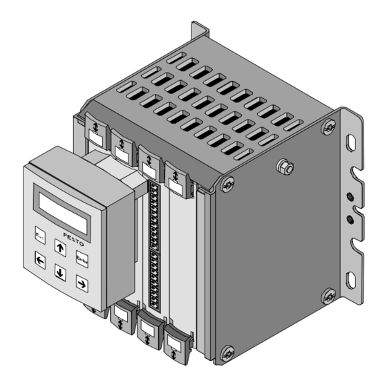
1. System summary 1.6 Commissioning and programming options The SPC200 can be commisssioned and programmed by means of the: – operating panel type SPC200-MMI-1 – WinPISA software package You can commission and program single and multi-axis systems by means of the control panel. WinPISA offers an extended scope of functions and a very user-friendly interface. - Page 38 Interface to the SPC200 on the rear Fig. 1/10: Operating panel type SPC200-MMI-1 The control panel offers all the functions necessary for commissioning, programming, diagnosis and operation directly on the SPC200. It also provides functions for editing position registers and programs. 1-25 SPC200... 9904a...
- Page 39 WinPISA The WinPISA software package runs on Windows 3.1 or higher. It provides a user-friendly interface. Tool bar Program window Project window Fig. 1/11: WinPISA user interface 1-26 SPC200... 9904a...
- Page 40 – user-friendly editor for NC programming, based on DIN 66025 – load functions for programs, projects, etc. – graphical function for analysing the positioning beha- viour WinPISA supports single-axis and multi-axis applica- tions with up to four axes. 1-27 SPC200... 9904a...
-
Page 41: I/O Address Range Of The Spc200
1. System summary 1.7 I/O address range of the SPC200 A complete word (16 bits) for inputs and/or outputs is available for each component and each I/O module, ir- respective of the number of I/Os which are integrated. Configuration of the SPC200... - Page 42 Q1.0 ... Q1.11 I1.0 ... I1.15 Q3.0 ... Q3.15 I3.0 ... I3.15 These I/Os are reserved partly by pre-assigned functions Q= output (control inputs and outputs) I = input Fig. 1/12: Address assignment without field bus module (example) 1-29 SPC200... 9904a...
- Page 43 1. System summary 1-30 SPC200... 9904a...
-
Page 44: Fitting
2. Fitting Chapter 2 Fitting SPC200... 9904a... - Page 45 2. Fitting Inserting and removing modules ........... 2-5 Mounting the basic unit ..............2-9 Fitting the control panel ............... 2-12 Fitting the axis interface and I/O function module ...... 2-14 Instructions on fitting the pneumatic axis ........2-19 SPC200... 9904a...
- Page 46 2. Fitting Contents of This chapter describes how to fit and remove SPC200 this chapter components as well as how to fit the following compo- nents: – the SPC200 basic unit – the control panel – the axis interface – the I/O function module This chapter also contains instructions on how to fit the pneumatic axis.
-
Page 47: Fitting
Before starting assembly work, switch off the follow- ing in the order specified: 1. the compressed air supply 2. the load and operating voltages on the SPC200 and if necessary, the load voltage supply on the axis interface string. By doing this you will avoid: –... -
Page 48: Inserting And Removing Modules
• Before inserting or removing modules you must ensure that you are electrostatically discharged to protect the modules against static discharges. The SPC200-CPU-... rack serves as a housing for the SPC200 modules. The SPC200 processor and memory are mounted on the integrated backplane. The modules plugged in are connected through this backplane. - Page 49 – If you are using a control panel, fit the stepping motor module and field bus module, if applicable, with at least one free slot between it/them and the diagnostic module. SPC200... 9904a...
- Page 50 2. Fitting WARNING Actuators can be accidentally activated and the SPC200 damaged, if modules are inserted or removed with the power switched on. Before installation or maintenance work switch off the following power sources in the following order: 1. compressed air supply 2.
- Page 51 2. Unscrew and remove the connecting cable on the front of the module. 3. Press both safety catches to unlock (see Fig. 2/1) and carefully pull out the module. 4. Close any unoccupied slots with blanking plates. SPC200... 9904a...
-
Page 52: Mounting The Basic Unit
– Screwing it directly to the wall of the cabinet. – Fastening it to a top hat rail. PLEASE NOTE Fit the SPC200 or the hat rail so that there is sufficent space for heat dissipation (at least 40 mm above and below). - Page 53 The rack is mounted on the top hat rail as follows: 1. Make sure that the surface on which the rack is to be located can bear the weight of the SPC200. 2. Fasten a top hat rail (mounting rail EN50022 - 35x7.5;...
- Page 54 2. Fitting M4 x 10 bolt Clamp Clip Fastening bolts Top hat rail Fig. 2/3: Rail mounting for the rack The procedure for removing the rack is as follows: 1. Remove the clamps. 2. Withdraw the rack. 2-11 SPC200... 9904a...
-
Page 55: Fitting The Control Panel
SPC200. Control panel type SPC200-MMI-1 can be plugged directly onto the diagnostic module type SPC200-MMI- DIAG of the SPC200 (see figure 2/4). Proceed with the fitting as follows: 1. Switch off the compressed air supply. 2. Switch off the operating voltage and the load voltage for the SPC200. - Page 56 Proceed as follows when dismantling: 1. Switch off the compressed air supply. 2. Switch off the operating voltage and the load voltage for the SPC200. 3. Carefully remove the control panel from the diagnostic module type SPC200-MMI-DIAG. 2-13 SPC200... 9904a...
-
Page 57: Fitting The Axis Interface And I/O Function Module
66 mm x 70 mm Vertical approx. 66 mm x 30 mm The dimensions for the four threaded holes for M4 size bolts and the installation of the angle brackets are shown in the following figure. 2-14 SPC200... 9904a... - Page 58 34 mm 81 mm 95 mm 30 mm Fitting the angle bracket horizontally Right-angle plug Fitting the angle bracket vertically Fig. 2/5: Installation of the SPC-AIF-... axis interface • Secure the axis interface with at least 3 bolts. 2-15 SPC200... 9904a...
- Page 59 The following diagram shows the positions of the four holes for the M4 screws. 67 mm INPUT/OUTPUT POWER DIAG 40 mm OUTPUT INPUT SPC-FIO-2E/2A-M8 I/O function module Fig. 2/6: Dimensions for installing I/O function module 2-16 SPC200... 9904a...
- Page 60 5. Tighten the bolts firmly. This will clamp the fastening and the housing firmly to the rail. Fastening M4x12 bolt Mounting rail Backing washer Housing Fig. 2/7: Fitting the SPC-FIO-2E/2A-M8 to a mounting rail 2-17 SPC200... 9904a...
- Page 61 2. Fitting The procedure for removing the device is as follows: 1. Loosen the bolts. 2. Remove the housing. 3. Lever the fastening out of the mounting rail using a screwdriver. Fastening Screwdriver Fig. 2/8: Dismantling the fastening 2-18 SPC200... 9904a...
-
Page 62: Instructions On Fitting The Pneumatic Axis
– If you wish to use a measuring system with slides under harsh environmental conditions, mount it so that the side with the control slides faces downwards. The drip edge on either side will then prevent ex- cessive soiling of the slide surfaces. 2-19 SPC200... 9904a... - Page 63 – The play between drive, guide, mass and measuring system must be smaller by a factor of 10 than the required tolerance (max. 0.1 mm). 2-20 SPC200... 9904a...
-
Page 64: Installation
3. Installation Chapter 3 Installation SPC200... 9904a... - Page 65 Connections of the diagnostic module ........3-30 3.3.4 Connections of I/O module SPC200-DIO-........3-33 3.3.5 Connections of analogue input module type SPC200-2AI-U..3-42 3.3.6 Connections on the subcontroller module type SPC200-SCU-AIF................ 3-45 Installing the modules on the axis interface string...... 3-47 3.4.1...
- Page 66 Contents of This chapter describes how to fit the pneumatic axis this chapter and how to fit the SPC200 basic unit with the following components and modules: – the power supply module type SPC200-PWR-AIF – the diagnostic module type SPC200-MMI-DIAG –...
-
Page 67: General Instructions On Installation
3. Installation 3.1 General instructions on installation CAUTION Use only the specially adapted components from Festo for setting up and wiring the system. Only in this way can you guarantee the correct functioning of the system. WARNING Switch-off the following in the order specified before carrying out installation and maintenance work: 1. -
Page 68: Instructions On Pneumatic Installation
3. Installation 3.2 Instructions on pneumatic installation PLEASE NOTE Observe the following instructions on pneumatic installation. Only then can you guarantee faultless operation. Instructions on installation see following pages Fig. 3/1: Summary of pneumatic installation SPC200... 9904a... - Page 69 Guide value: twice the standard rated flow of the valve (MPYE). – Use a microfilter if you cannot avoid a small amount of oil mist emerging from the compressed air source. SPC200... 9904a...
- Page 70 • Use only straight connectors. If angled connectors cannot be avoided, use plug connectors from the Festo Quick Star series. • Use connectors with as large a width as possible. If the connections of the valve and the cylinder are not the same size, select the largest possible width for the smaller size.
- Page 71 = 2 * V = Buffer volume; * π * L = Cylinder volume (V = Cylinder stroke length = Cylinder diameter / 2 SPC200... 9904a...
- Page 72 Recommendation: Use only suitable cylinder-valve combinations. The diagram below shows permitted pro- portional directional control valves for cylinders of type DGP...-... and DGO-..Proportional directional control valve type MPYE-5-...-010B Cylinder diameter Cylinder length Fig. 3/2: Suitable valve/cylinder combination SPC200... 9904a...
- Page 73 Instructions on connecting the tubing with slide and yoke operation can be found in section 3.2.2. Instruc- tions on the pneumatic emergency stop circuit can be found in section 3.2.1. • Use silencers with high nominal flow rate (e.g. U-1/8). 3-10 SPC200... 9904a...
- Page 74 Use only permitted cylinders of type DGP...-... or DGO- ... with suitable guide. Other cylinders may only be used after agreement with Festo. Use maximum 80% of the cylinder length as the work- ing stroke. In the case of cylinders with adjustable cushioning (...-PPV), the working stroke must not pro-...
- Page 75 – If required, select an adequately large energy supply in order to minimise the effect of bending forces on the positioning behaviour. 3-12 SPC200... 9904a...
- Page 76 (1-2/3 sin α) * m diagonal 0.1 * m (0° < α < 90°) α = Fitting position in [°] * 0.008 = Cylinder diameter [mm] = Supply pressure [bar] = maximum mass load for horizontal fitting position [kg] 3-13 SPC200... 9904a...
- Page 77 • Fit the linear potentiometer so that it is electrically insulated from the mounting surface. Use the clamp- ing brackets provided. PLEASE NOTE The positioning accuracy which can be achieved de- pends on the type of measuring system used. 3-14 SPC200... 9904a...
-
Page 78: Pneumatic Emergency Stop Circuit
– Cylinder at zero pressure during emergency stop – Piston clamped during emergency stop – Piston moves throttled to the left or right end position during emergency stop. 3-15 SPC200... 9904a... - Page 79 Emergency stop with shut-off valve To switch the operating pressure on and off a shut-off valve can be fitted between the maintenance unit and the proportional directional control valve. Shut-off valve for emergency stop Fig. 3/6: Switching off the operating pressure 3-16 SPC200... 9904a...
- Page 80 3. Installation Universal emergency stop circuit Fig. 3/7: Universal emergency stop circuit 3-17 SPC200... 9904a...
- Page 81 Connect compressed air Connect flow control valve with silencer Left end position Connect flow control valve with Connect compressed air silencer 1) Flow control valves reduce the impact force if an EMERGNCY STOP valve does not function correctly. 3-18 SPC200... 9904a...
-
Page 82: Tubing For Slide And Yoke Operation
If the valve is mounted parallel to the measuring system operation and the tubing is not to be crossed, the electrical con- nections of the two devices must be on the same side. Electrical connection Fig. 3/8: Tubing in slide operation 3-19 SPC200... 9904a... - Page 83 (compare figs. 3.8 and 3.9). Electrical connection Fig. 3/9: Tubing in yoke operation with measuring system 3-20 SPC200... 9904a...
-
Page 84: Installing The Spc200
– undesired movements of the connected actuators – uncontrolled movement of loose tubing – undefined switching states. PLEASE NOTE Mark the cables connected to the SPC200. In this way you can avoid confusion with similar plugs during conversion work. 3-21... -
Page 85: Selecting The Power Unit
(protection against direct and indirect contact) in accordance with EN 60204-1/IEC 204 is guaranteed on Festo valve terminals. Safety transformers with the ad- jacent designation must be used for supplying PELV networks. The valve terminals must be earthed in order to ensure their function (e.g. - Page 86 3. Installation Current consumption at pin 1 of module SPC200-PWR-AIF Current consumption of basic load of the electronic 500 mA components Load current consumption of simultaneously acti- + _____ A vated outputs on module SPC200-DIO Sum of load current consumption of all proportional + _____ A directional control valves (appprox.
-
Page 87: Connections Of The Power Supply Module
3. Installation 3.3.2 Connections of the power supply module On the front of power supply module type SPC200- PWR-AIF you will find the following connecting and dis- play elements: Power supply module type SPC200-PWR-AIF Combicon screw terminal for axis interface string (X1) - Page 88 1: + 24 V DC, tolerance -5 %/+25 % – the internal electronics of the SPC200, of the con- nected modules and measuring systems; pin 2: + 24 V DC, tolerance -5 %/+25 %...
- Page 89 24 V: 24 V supply for internal electronics Earth/ground connection (M4 thread) Fig. 3/11: Operating voltage connection (X2) Earth/ground The SPC200 has earth connections on the left and right connection hand sides of the rack. PLEASE NOTE Connect one of the earth cables of the SPC200 with low impedance (short cable with large cross- sectional area) to the earth potential.
- Page 90 0 V 24 V 24 L 24 V Load supply (can be switched off separately) Fig. 3/12: Example – Connecting a common 24 V power supply 3-27 SPC200... 9904a...
- Page 91 Note the maximum permitted cable lengths on the axis interface string (see section 3.4). In this way you will avoid faults in the SPC200 and in the modules connected to the axis interface string. The bus signals, the operating voltage and the load voltage for the connected field devices are provided via the 5-pin plug of the power supply module.
- Page 92 0 V (green) CAN-HIGH (white) 24 V load voltage (grey) 24 V (yellow) Earth connection Fig. 3/13: Pin assignment of the plug for the first axis interface string (X1) Connect the cable screening to the earth connection 3-29 SPC200... 9904a...
-
Page 93: Connections Of The Diagnostic Module
3. Installation 3.3.3 Connections of the diagnostic module You will require a diagnostic module type SPC200-MMI- DIAG for commissioning, programming and diagnosing. This diagnostic module offers the following serial inter- faces: – a connection for control panel type SPC-MMI-1; – a connection for a PC. This serial interface is de- signed as a 9-pin Submin-D plug and complies with standard RS-232. - Page 94 Fig. 3/13: Pin assignment of serial interface (X4) Connect the diagnostic cable as follows: – the 9-pin plug to the 9-pin socket on the diagnostic module – 25-pin or 9-pin socket on the serial interface of your 3-31 SPC200... 9904a...
- Page 95 3. Installation The control panel type SPC200-MMI-1 can be placed directly on the upper interface when the power supply is switched off. CAUTION The control panel may be damaged if it is placed on the interface when the power supply is switched on.
-
Page 96: Connections Of I/O Module Spc200-Dio
3. Installation 3.3.4 Connections of I/O module SPC200-DIO-... You will require an I/O module type SPC200-DIO-..for controlling the SPC200 via digital I/Os. This I/O module has 10 digital inputs and 8 digital outputs for the follow- ing functions: – providing digital I/Os for controlling the SPC200 (only if no field bus module is fitted) –... - Page 97 0 V (non floating) 0: input 0 " 9: input 9 Fig. 3/16: Assignment of plug X5/X7 (inputs) 24 V ± 25 % 24 V Three-wire sensor Contact Two-wire sensor Fig. 3/17: Example of circuitry (PNP inputs) 3-34 SPC200... 9904a...
- Page 98 24 V Example 1 Not permitted Example 2 Load voltage Fig. 3/19: Example of circuitry (outputs X6/X8) How to supply the load voltage for plugs X2 and X6/X8 via one power unit is shown in Fig. 4/1. 3-35 SPC200... 9904a...
- Page 99 3. Installation Addressing The assignment of the I/O address range depends on the configuration of the SPC200. If a field bus module is fitted, the address range 0.0 ... 0.9 will remain unas- signed. The assignment of I/O addresses for configura- tion with and without a field bus module is shown in the following table.
- Page 100 I/Os for control- ling the SPC200 (I0.0 ... I0.9 and Q0.0 ... Q0.7). The I/Os of further I/O modules are freely programmable. – If a field bus module is fitted, the address ranges (I0.0 ...
- Page 101 RESET I0.9 ENABLE ENABLE 1) Designation on the module 2) Addresses of the first installed I/O module with configuration without field bus module (I = input) 3) RESET (Program reset) in conjunction with 0-signal at STOP input 3-38 SPC200... 9904a...
- Page 102 0 V external supply for outputs 1) Designation on the module 2) Addresses of the first installed I/O module with configuration without field bus module (Q = output) 3) No freely programmable I/Os are supported in this operating mode 3-39 SPC200... 9904a...
- Page 103 3. Installation General pin assignments for I/O modules without spe- cial control functions The word number (here x) depends on the configura- tion of the SPC200. Configuration Word number x Without With field bus module field bus module Second I/O module...
- Page 104 3. Installation General pin assignments for I/O modules without spe- cial control functions The word number (here x) depends on the configura- tion of the SPC200. Configuration Word number x Without With field bus module field bus module Second I/O module...
-
Page 105: Connections Of Analogue Input Module Type Spc200-2Ai-U
A1-: signal (-) A2-: signal (-) Earth connection Fig. 3/20: Reference input value module type SPC200-2AI-U (X9) The analogue inputs can be assigned to any axes and activated by appropriate commands in the positioning program. Several reference input values are supported by this program (e.g. - Page 106 • Always connect the screening for analogue signal cables on one side to the earth conductor (pin 9). Recommendation: Use short signal cables wherever possible. The maximum length of the cable should not exceed 4 m. 3-43 SPC200... 9904a...
- Page 107 SPC200-2AI-U A1- [A2-] A1+ [A2+] Signal (-) Screening/shield Signal (+) Earth conductor Fig. 3/21: Connecting a differential signal Circuitry for connecting a potentiometer SPC200-2AI-U A1+ [A2+] A1- [A2-] Potentiometer Earth conductor Screening/shield Fig. 3/22: Connecting a potentiometer 3-44 SPC200... 9904a...
-
Page 108: Connections On The Subcontroller Module Type Spc200-Scu-Aif
3. Installation 3.3.6 Connections on the subcontroller module type SPC200-SCU-AIF In its basic design, the SPC200 can control the posi- tioning of two pneumatic axes. With the subcontroller module, maximum four pneumatic axes can be oper- ated with just one SPC200. The subcontroller module provides a connection for a second axis interface string and controls the positioning of the connected axes. - Page 109 In order to avoid confusion between connections X10 and X1, assign different codes to the connections. In- sert the coding pins supplied into different grooves in the connector strips. Remove the appropriate plastic lugs from the relevant plugs. 3-46 SPC200... 9904a...
-
Page 110: Installing The Modules On The Axis Interface String
- proportional directional control valve cable. PLEASE NOTE Connect the earth/ground connection of the modules with low impedance (short cable with large diameter) to the earth potential. In this way, you will avoid interference caused by elec- tromagnetic influences. 3-47 SPC200... 9904a... - Page 111 3) Configuration on the axis interface string – At first, maximum two axis interfaces are connected to the SPC200. If required, the I/O function module or at first a CP module with outputs and then a CP module with inputs can be connected to the last axis interface.
- Page 112 2 m max. 8 m 1) Without external load voltage supply 2) Without external load voltage supply only type CPV10-VI-FB-6 or type CPV14-VI-FB-6 is permitted Fig. 3/24: Maximum permitted cable lengths on the axis interface string (single-axis systems) 3-49 SPC200... 9904a...
- Page 113 SPC-AIF-... SPC-AIF-SUP-24V SPC-AIF-SUP-24V SPC-AIF-SUP-24V SPC-FIO-2E/2A CPV-...-VI-FB-... CPV-...-VI-FB-... CP-E16-M... CP-E16-M... max. 8 m max. 5 m max. 8 m 1) Without external load voltage supply Fig. 3/25: Maximum permitted cable lengths on the axis interface string (two-axis systems) 3-50 SPC200... 9904a...
-
Page 114: Installing The Axis Interface Spc-Aif
– Seal any unused connectors with the protective caps provided. Only then is the IP 65 type of protection ensured. PLEASE NOTE Maximum two axis interfaces may be connected to an axis interface string. Interface types for different measuring systems may be mixed here. 3-51 SPC200... 9904a... - Page 115 3. Installation The axis interface forms the connection between the components on the axis and the SPC200. It loads the values supplied by the measuring system and passes these on to the SPC200. It also transmits the received positioning values in analogue form to the proportional directional control valve.
- Page 116 3. Installation Connecting the axis interface to the SPC200 WARNING Observe the maximum permitted cable lengths between the individual modules on the axis interface string and the SPC200 (see section 3.4). Use only the original cables mentioned below for connecting the axis interface.
- Page 117 The measuring system cable is connected to the axis interface. It has a fixed cable length of approx. 0.30 m. PLEASE NOTE Use only the original cable. Do not lengthen the cable. By keeping the cable short, you can avoid faults due to electromagnetic interference. 3-54 SPC200... 9904a...
- Page 118 Socket for valve KMPYE-... (MPYE) on cable KMPYE-... (brown) (green) Nominal value V(s) (yellow) (grey) Not connected (pink) n.c. 24 V supply for valve (white) 24 V supply for valve (blue) not connected (red) n.c. Fig. 3/27: Valve connection 3-55 SPC200... 9904a...
-
Page 119: Installing I/O Function Module Spc-Fio-2E/2A-M8
Use cable type M8-GSGD-... for connecting sensors and actuators and plugs with union nuts of thread size M8x1. Close off any unused connections with the pro- tective caps supplied with the module. This is the mini- mum required to comply with IP65. 3-56 SPC200... 9904a... - Page 120 Groove for labels (ISB6x10) Status LED (green) Actuator connections (outputs) Protective cap Status LED per output (yellow) Earth connection Status LED per input (green) Type plate Sensor connections (inputs) Fig. 3/28: Connections on I/O function module SPC-FIO-2E/2A-M8 3-57 SPC200... 9904a...
- Page 121 Pin 3: 0 V 1) module on AIF string 1: x=1; module on AIF string 2: x=3 Fig. 3/29: Pin assignment of the outputs Example 1 Not permitted Example 2 Fig. 3/30: Example of circuitry for outputs (PNP) 3-58 SPC200... 9904a...
- Page 122 Pin 3: 0 V 1) module on AIF string 1: x=1; module on AIF string 2: x=3 Fig. 3/31: Pin assignment of inputs Three-wire sensor (positive switching) Contact Two-wire sensor (positive switching) Fig. 3/32: Example of circuitry for inputs (PNP) 3-59 SPC200... 9904a...
- Page 123 3. Installation 3-60 SPC200... 9904a...
-
Page 124: Commissioning
4. Commissioning Chapter 4 Commissioning SPC200... 9904a... - Page 125 Procedure for commissioning ............4-5 Connecting a single axis system for initial commissioning ... 4-9 Commissioning via the control panel .......... 4-16 4.3.1 Saving the hardware configuration..........4-16 4.3.2 Commissioning pneumatic axes..........4-20 4.3.3 Instructions on commissioning multi-axis systems...... 4-38 SPC200... 9904a...
- Page 126 Contents of This chapter deals with the commissioning of a pneu- this chapter matic axis together with the SPC200 by means of con- trol panel type SPC200-MMI-1. Commissioning is described using, as an example, a single axis system with control via an I/O module. The...
-
Page 127: Commissioning
– uncontrollable movements of loose tubing. – undefined switching states. CAUTION The SPC200 is factory set to certain axis and appli- cation parameters. Before supplying compressed air, these settings must be adjusted to suit your applica- tion and the axes which you are using. -
Page 128: Procedure For Commissioning
SPC200. You should make the necessary settings with: • the control panel •... - Page 129 3. Commission the connected axes (section 4.3.2). 4. Commission the complete system. When the hardware configuration had been saved, the individual axes can be configured and commissioned. The following list shows the steps which are necessary for commissioning penueumatic axes. SPC200... 9904a...
- Page 130 (see section 4.3.2, step 4). 5. Move the axis manually (optional). In this way you can check the functioning of the controller as well as the effectiveness of the set software end positions (see section 4.3.2, step 5). SPC200... 9904a...
- Page 131 The steps required depend on the equipment fitted in the positioning system. The next section deals with the commissioning of a pneumatic axis using the example of a single-axis sys- tem without a field bus module. SPC200... 9904a...
-
Page 132: Connecting A Single Axis System For Initial Commissioning
If a fieldbus module is not installed If a fieldbus module is not installed, the control signals will be triggered via the first installed I/O module. The following connection diagram shows the circuitry re- quired in this case. SPC200... 9904a... - Page 133 RELEASE STOP 24 V RESET Designation on plug X5 Function Input address Load supply (can be switched of separately) 1) RESET (Program reset) in conjunction with 0-signal at STOP input Fig. 4/1: Connection diagram for initial commissioning 4-10 SPC200... 9904a...
- Page 134 4. Commissioning CAUTION • Leave the compressed air supply switched off. • The SPC200 is factory set to certain axis and application parameters. Before you apply com- pressed air you must adjust these settings to your application and to the axes which you are using.
- Page 135 – the controller to be switched off and the valve control voltage to be reduced to an electrical medium value (Offset). No further movement orders will then be accepted. – the READY output on the SPC200 will be reset (see Fig. 4/2). 4-12 SPC200... 9904a...
- Page 136 4. Commissioning ENABLE input on the SPC200 Reaction time of the SPC200 READY output on the SPC200 - without stepping motor module: max. 10 ms Reaction time max. 10 ms - with stepping motor module: max. 2 sec. 1 = 1-signal = 24 V; 0 = 0-signal = 0 V Fig.
- Page 137 Make sure that no one can reach into the range of movement of the moving object and that no protruding objects are in the way. – Switch on the power supply to the SPC200 and the load supply. After applying the supply voltage, the SPC200 will auto- matically carry out an internal test.
- Page 138 SPC200 Vnnn XY SELECT WITH <> Enter Operating version of the SPC200 (nnn = version number) Currently configured axes (here X and Y axes) Note: Use the <- -> keys to make your selection. Fig. 4/3: Initial display of the control panel...
-
Page 139: Commissioning Via The Control Panel
Then proceed as follows: 4.3.1 Saving the hardware configuration When the SPC200 is switched on, it assigns the axis identification to the connected axes one after the other. If modifications are made later to the axis configuration, the axis identifications will be reassigned. - Page 140 To prepare for commissioning you must create and configuration save the desired hardware configuration. The SPC200 is prepared at the factory for automatically saving the current hardware configuration during the first starting phase. If you have connected the modules to the axis interface string correctly before switching on the first time, it will not be necessary to save the hard- ware configuration manually.
- Page 141 5. If the actual configuration recognized is what you desire, press any key to ackknowledge the error message. The basic setting will then be shown again. 4-18 SPC200... 9904a...
- Page 142 9. Press the ESC key in order to discontinue. Or press the keys Enter in order to delete all the data in the SPC200 and to save the hardware configuration. When the actual hardware configuration is saved, the actual configuration will become the reference configu- ration.
-
Page 143: Commissioning Pneumatic Axes
Leave the supply pressure switched off and proceed as described in Section 6.2 "Setting project-specific parameters". When the SPC200 is commissioned the first time, there must be a rising edge at the Enable input for controller enable after the project-specific parameters have been set. - Page 144 3 bar. By doing this you will avoid: – damage to the axis in the event of operating errors. 4-21 SPC200... 9904a...
- Page 145 Enter key. The first command in the sub- menu AXIS will then be shown. TEST/DIAG. AXIS JOG AXIS > 5. Now select the command MOVEMENT TEST with the keys ← →. TEST/DIAG. AXIS MOVEMENT TEST > 4-22 SPC200... 9904a...
- Page 146 (see under 7). Correct the tubing con- nections if the slide does not move in the appropriate direction (see also section 3.2.2). By pressing the ESC key several times, you can return to the initial display. 4-23 SPC200... 9904a...
- Page 147 In these cases, there- fore, new identification travel is necessary. During identification travel, characteristic values of the system are ascertained and saved. Before identification travel can be carried out, the positioning system must be ready for operation. 4-24 SPC200... 9904a...
- Page 148 Dynamic idnetification is also a requirement for the NC command G00. If your compressed air supply does not reliably fulfil the requirements (tolerance of ± 1 bar in operation), please refer to the instructions in section A.3.1. 4-25 SPC200... 9904a...
- Page 149 In the course of the dynamic identification an axis of the system will be set in motion at the highest ac- celeration and speed. Make sure that: - the complete positioning range of the axis is free - the correct axis and application parameters are set. 4-26 SPC200... 9904a...
- Page 150 Enter key. The first command in the sub- menu AXIS will then be shown. TEST/DIAG. AXIS JOG AXIS > 5. Now select the command IDENTIFICATION with the keys ← → . TEST/DIAG. AXIS IDENITFICATION > 4-27 SPC200... 9904a...
- Page 151 By pressing the ESC key several times, you can return to the initial display. If identification fails • Check the set-up, the installation as well as the axis and application parameters of the relevant axis. Then carry out identification again. 4-28 SPC200... 9904a...
- Page 152 Calibration smooths out system-related tolerances which may arise in determining the current position. In this way the electrically-determined position values are matched to the actual measurements. Carry out the calibration when you want to ensure or improve the absolute positioning accuracy. 4-29 SPC200... 9904a...
- Page 153 AXIS will then be shown. TEST/DIAG. AXIS JOG AXIS > 3. Press the Enter key to select the command. The se- lected axis and the current positioning mode will then be shown. JOG AXIS X: CONT 4-30 SPC200... 9904a...
- Page 154 7. With movement mode STEP: Press the enter key to move one step. With movement mode CONT: Hold enter key pressed down whilst movement is carried out. By pressing the ESC key several times, you can return to the initial display. 4-31 SPC200... 9904a...
- Page 155 Apply 1-signal to the See also STOP input (I0.7). section 4.2 Proportional directional Replace the First check control valve is proportional directional with defective. control valve. MOVEMENT TEST *) Check and replace if necessary (see also chapter 8). 4-32 SPC200... 9904a...
- Page 156 Enter a short test program, e.g.: N000 G02 ... X+100 FX50 N001 G02 ... X+150 FX90 N002 M30 Adapt the position specifications (X+100, Y+150) to your requirements, where necessary. Instructions on programming with the control panel can be found in section 6.3. 4-33 SPC200... 9904a...
- Page 157 OPERATING MODE RECORD SELECT 3. Select the operating mode START/STOP and press the Enter key. The operating mode then becomes effective. OPERATING MODE START/STOP By pressing the ESC key several times, you can return to the initial display. 4-34 SPC200... 9904a...
- Page 158 NC record will then be shown. SINGLE STEP N000 4. Press the Enter key to start the NC record. The NC record will then be processed. The current record number will be shown in the bottom line. 4-35 SPC200... 9904a...
- Page 159 4. Commissioning 5. Repeat point 4 if you wish to start the NC record shown. By pressing the ESC key several times, you can return to the initial display. 4-36 SPC200... 9904a...
- Page 160 Program 0 is defined as the starting program at the factory. PLEASE NOTE When defining starting programs observe the instruc- tions in section 7.1. In order to improve the positioning characteristics, you can optimize the controller parameters after the com- missioning (see Appendix A). 4-37 SPC200... 9904a...
-
Page 161: Instructions On Commissioning Multi-Axis Systems
Please note when using two starting programs that both parallel running programs together have the output READY and the inputs ENABLE, STOP and START/ RESET. Instructions on coordinated and autonomous modes of two axes can be found in section 7.1.1. 4-38 SPC200... 9904a... -
Page 162: Controlling The Spc200
5. Controlling the SPC200 Chapter 5 Controlling the SPC200 SPC200... 9904a... - Page 163 5. Controlling the SPC200 Contents 5. Controlling the SPC200 General instrutions on operation ........... 5-4 Start/stop mode ................5-9 5.2.1 Explanation of all I/O signals in start/stop mode......5-11 Record select mode..............5-17 5.3.1 Description of all I/O signals in record select mode ....5-22...
- Page 164 Information on the coordinated and autonomous oper- information ation of axes with an SPC200 can be found in chapter 7. Special instructions on operation with the field bus or the operation of electric axes can be found in the ma- nual for the relevant extension module.
-
Page 165: General Instrutions On Operation
The record select operating mode supports the close select coupling of the SPC200 with a host PLC/IPC. If control is via an I/O module, 32 NC records of the fixed starting programs can be accessed via 5 digital inputs. In this... - Page 166 ERROR LED goes out System enable? (I0.9) READY output is set Closed loop controller is switched on Current position = Reference position (controlled stop) SPC200 is ready for operation Dependent on error (see chapter on diagnosis) Fig. 5/1: SPC200 switch-on procedure SPC200... 9904a...
- Page 167 Switch on the load voltage before setting ENABLE to a 1-signal. When the power supply is switched on, the SPC200 carries out initialising and self test. If there is no fault, the set operating mode will be activated and the start- ing programs will be made available.
- Page 168 READY STOP START/CLK Load voltage should be applied (typ. > 1 Sek.) Reaction time of the SPC200: - without stepping motor module: max. 10 ms - with stepping motor module: max. 2 sec. Debouncing time t ≥ 10 ms Fig. 5/2: Time behaviour of I/O signals when processing is started...
- Page 169 5. Controlling the SPC200 Acknowledging a fault If a fault occurs whilst the program is being processed, the READY output will be reset automatically. When the error has been eliminated, the error massage can be acknowledged by a START signal. If there are several errors at the same time, you must quit each individual error.
-
Page 170: Start/Stop Mode
5. Controlling the SPC200 5.2 Start/stop mode In the start/stop mode the SPC200 is capable of con- trolling positioning tasks on its own. For this purpose, this operating mode provides the following even when only one I/O module is used: –... - Page 171 5. Controlling the SPC200 24 V I0.9 I0.8 I0.7 START/ ENABLE STOP 24 V RESET 24 V Q0.3 Q0.7 MC_A READY 24 V Designation on the X5 plug Designation on the X6 plug Input address (I = input) Output address (Q = output)
-
Page 172: Explanation Of All I/O Signals In Start/Stop Mode
Synchronization input for program A This input supports synchronization of the SPC200 with external devices (e.g. PLC/IPC). With a Programmed stop (command M00), the SPC200 waits for a falling edge at this input before it processes the next NC record (see Fig. 5.5). STOP... - Page 173 5. Controlling the SPC200 Inputs Function Description START/ Start/continue programs RESET A positive edge on this input will cause the program run to be started or continued. Requirements: - 1-signal on the STOP input - 1-signal on the ENABLE input...
- Page 174 5. Controlling the SPC200 Outputs Function Description MC_B MC output for program B (motion (as MC_A, but for program B) complete) MC_A MC output for program A (motion 24 V at this output shows that a positioning command from program A is complete) completed.
- Page 175 (command M00). If there is a 1 signal at the corresponding SYNC input (SYNC_IA or SYNC_IB), the SPC200 will signals the stop status of the program by setting the corresponding SYNC output (SYNC_OA or SYNC_OB). Externally controlled processes can then be run.
- Page 176 5. Controlling the SPC200 With a negative edge on the SYNC input the SYNC output is reset and the program run continues. The con- tinuation of the program run is represented in Fig. 5.5 with the aid of the MC signal.
- Page 177 5. Controlling the SPC200 Summary of start/stop mode In the start/stop operating mode the SPC200 provides freely programmable inputs and outputs. With the pro- grammed stop (command M00) two programs running in parallel independently of one another, e.g. through a PLC/IPC, can be synchronised with other processes.
-
Page 178: Record Select Mode
5. Controlling the SPC200 5.3 Record select mode Record In the record select mode the SPC200 is controlled by select mode a host PLC/IPC. The controlling PLC/IPC passes on positioning commands to the SPC200 in the form of bi- nary coded record numbers through digital I/Os. The SPC200 then executes the desired NC record and awaits the next positioning task. - Page 179 5. Controlling the SPC200 Only purely positioning commands, positioning conditions and commands for setting the quality class are supported. These are: Descripiton command Move to position at highest possible speed Move to position at specified speed Move smoothly to position at specified speed...
- Page 180 5. Controlling the SPC200 24 V I0.9 I0.8 I0.7 I0.0/I0.4 I0.5/I0.6 ENABLE RESET STOP 24 V REC_BIT... CLK_A/B 24 V Q0.3/Q0.4 Q0.5/Q0.6 Q0.7 24 V RC_A/B ACK_A/B READY Designation on plug X5 Function Input address (I = input) Outputs of the PLC/IPC...
- Page 181 In the Record select mode, positioning tasks in the form of binary coded NC record numbers can be sent to the SPC200 via the inputs REC_BIT..The record num- bers will be accepted for the corresponding program on a positive edge at the CLK input and acknowledged with the ACK signal.
- Page 182 0 ... 999 1) Maximum permitted number of NC records The NC records are stored in the SPC200 always be- ginning with NC record 0 and step size 1. If possible, use the same numbering in WinPISA, e.g. with the aid of the numbering function.
-
Page 183: Description Of All I/O Signals In Record Select Mode
Start positioning order from program A If there is a rising edge at this input, the NC record number at the inputs RECBIT... will be accepted by the SPC200 for program A and processed. This will be indicated by the signal ACK_A (see Fig. 5.7). - Page 184 5. Controlling the SPC200 Inputs Function Description RESET Reset the program (RESET) If there is 1-signal on the ENABLE input and 0-signal on the STOP input, a RESET (program reset) can be triggered by rising edge at the RESET input. This causes the following:...
- Page 185 5. Controlling the SPC200 Outputs Function Description RC_B NC record from program B concluded (record com- (as RC_A, but for program B) plete) RC_A NC record from program A concluded (record com- A 1-signal on this output indicates that a positioning task from program plete) A has been completed.
- Page 186 5. Controlling the SPC200 Summary of record select mode The record select mode supports close coupling of the SPC200 with a higher-order PLC/IPC. Requirements - Program in program memory - System parameters entered in configuration - Record select mode set...
- Page 187 5. Controlling the SPC200 Programing example for record select mode Inputs NC records of starting program I0.4...I0.0 I11.12...I11.8 00000 N000 X100.00 Y100.00 – 00001 N001 X130.00 Y100.00 – 00010 N002 X50.00 FX50 – 01000 N008 X100.00 Y110.00 – 01001 N009 X10.00...
-
Page 188: Operation Of The Spc200 Via The Control Panel
6. Operation of the SPC200 via the control panel Chapter 6 Operation of the SPC200 via the control panel SPC200... 9904a... - Page 189 6. Operation of the SPC200 via the control panel Contents 6. Operation of the SPC200 via the control panel Layout and functions of the control panel ........6-4 6.1.1 Moving around the menu system ..........6-8 6.2. Setting project-specific parameters ..........6-14 Editing programs................
- Page 190 6. Operation of the SPC200 via the control panel Contents of This chapter deals with the menu and operating func- this chapter tions of the control panel type SPC200-MMI-..All the parameters and operating functions of pneumatic axes are described in detail and general system opera- ting functions are also described.
-
Page 191: Layout And Functions Of The Control Panel
6.1 Layout and functions of the control panel The SPC200-MMI plug-in control panel allows you to carry out commissioning, programming and diagnosis directly on the SPC200. It offers a simple menu struc- ture and a universal keymap. The following illustration shows the elements of the control panel. - Page 192 6. Operation of the SPC200 via the control panel The two-line LCD display shows all texts in English. Each line displays a maximum of 16 characters. The touch-sensitive keyboard consists of 6 keys. With these keys you can carry out all of the menu-driven functions and settings.
- Page 193 6. Operation of the SPC200 via the control panel Switching-on procedure After switching on the power supply the SPC200 automatically performs an internal test. During the brief test phase, the control panel displays the software ver- sion number of the control panel (here Vn.n).
- Page 194 SPC200 Vnnn X SELECT WITH <> Enter Operating system version of the SPC200 (nnn = Version number Currently configured axis (here X-axis) Prompt line: Make your menu selection with ← →. The point after the main version marker is not shown due to lack of space;...
-
Page 195: Moving Around The Menu System
6. Operation of the SPC200 via the control panel 6.1.1 Moving around the menu system SPC200 Vnnn X SELECT WITH <> SYSTEM DISPLAY EDIT CONFIG. CONTROL PROGRAM SYSTEM START SYSTEM NEW PROGRAM STOP SYSTEM MODIFY PROGRAM RESET SYSTEM DELETE PROGRAM RESET PROGRAMS MODIFY POSREG. - Page 196 6. Operation of the SPC200 via the control panel AXIS APPLIC. CONTROL. TEST/DIAG. PARAM. PARAM. PARAM. X,Y,Z,U X,Y,Z,U X,Y,Z,U Pneum. Electr. CYL. TYPE axis axis GAIN FACTOR SYSTEM CYL. LENGTH DAMPING FACTOR AXIS CYL. DIAMETER FILTER FACTOR X,Y,Z,U SENSORMEASUREM. POS. TIMEOUT...
- Page 197 6. Operation of the SPC200 via the control panel The menus on the control panel Menu Description System control: SPC200 READY Control functions Start, Stop, Reset SYSTEM CONTROL > Display: SPC200 READY Operands, System status DISPLAY > Edit programs: SPC200 READY...
- Page 198 6. Operation of the SPC200 via the control panel In selecting, the upper line will serve to orient you. It shows, e.g. the menu in which you are located. The lower line offers the selections which are possible in the current menu.
- Page 199 6. Operation of the SPC200 via the control panel The upper line then shows the previous selection for guidance. The lower line again shows the current possible selection or the input field in the lowest level. In the case of menus which contain axis-specific par- ameters or operating functions, the axis identifier of the first axis (X) will be shown when the menu is opened.
- Page 200 6. Operation of the SPC200 via the control panel In selecting a menu command or parameter proceed as follows: 1. Press the ESC key repeatedly until the initial display is shown. The first line of the display then shows the text SPC200 followed by the version number of the operating system.
-
Page 201: Setting Project-Specific Parameters
Incorrectly set parameters can lead to uncontrolled behaviour of the connected axes during operation. The SPC200 must be aware of the conditions of use governing your project and the type of components used in your positioning system. The necessary settings... - Page 202 6. Operation of the SPC200 via the control panel Procedure If you have selected a parameter in a menu by press- ing the Enter key (see Section 6.1.1), the text in the display will scroll up. AXIS PARAM. AXIS PARAM.
- Page 203 6. Operation of the SPC200 via the control panel The appropriate axis must be connected to the SPC200 and the current hardware configuration must be saved. With the keys ↑ and ↓, you can select the axis, the parameters of which you wish to modify. When the axis has been selected, the current parameter setting will be shown in the bottom line.
- Page 204 Fig. 6/6: Set parameter value The symbol ? indicates that the intended setting is ac- cepted into the SPC200 only when the Enter key is pressed. After pressing the Enter key, the ? is deleted. This indicates that the setting was accepted.
- Page 205 6. Operation of the SPC200 via the control panel Axis parameters AXIS PARAM The axis parameters are configuration parameters menu which describe the configuration, the properties and the components of the axis being used. The axis par- ameters form the basis for parameter ranges of the ap- plication parameters (e.g.
- Page 206 6. Operation of the SPC200 via the control panel Axis parameters for electric axes: AXIS PARAM menu (axis parameters) Electric axis CYL. LENGTH Cylinder length 50...3200 [mm] Y:+0050.00 1) Explanations see manual for stepping motor indexer module type P.BE-SMX-1-... Application parameters APPLIC.
- Page 207 6. Operation of the SPC200 via the control panel APPLIC. PARAM menu (application parameters) Pneumatic axis PRESSURE Supply pressure 3...10 bar X:+0000.00 Indicates the available supply pressure. For good positioning behaviour: during movement in front of the proportional directional control valve pressure deviations of max.
- Page 208 6. Operation of the SPC200 via the control panel Measuring system basepoint Lower software end position Cylinder basepoint Upper software end position Position basepoint (Project zero point) Fig. 6/7: Reference points APPLIC. PARAM menu (application parameters) Pneumatic axis FITTING OFFS.
- Page 209 6. Operation of the SPC200 via the control panel APPLIC. PARAM menu (application parameters) Pneumatic axis LOWER END POS. Lower software end position 0.0...3200 [mm] X:+0000.00 End position on the side of the measuring system base point which is monitored by the SPC200 operating system (software) and should not be exceeded.
- Page 210 6. Operation of the SPC200 via the control panel APPLIC. PARAM menu (application parameters) Pneumatic axis QUALITY CLASS Quality class 1...6 Describes the conditions under which a movement command should be considered as terminated or when the MC (Motion Complete) signal should be issued. Where:...
- Page 211 6. Operation of the SPC200 via the control panel Application parameters for electric axes: APPLIC. PARAM menu (application parameters) Electric axis RESOLUTION Resolution 0.100...9999.999 [1/mm] Y:+0010.000 START/STOP FR. Start-stop frequency 1 .. 9999 [Hz] Y:+0500.00 POS. BASEPOINT Project basepoint 0.0 .. 3200.0 [mm] Y:+0000.00...
- Page 212 6. Operation of the SPC200 via the control panel System configuration CONFIG. Enter the desired type of operation and the starting pro- SYSTEM grams for your system in the CONFIG. SYSTEM menu. menu Description of the individual parameters CONFIG. SYSTEM menu (configure system) ACTUAL CONFIGUR.
- Page 213 If the cursor is positioned at P, you can switch between P00 and P- - for task B. One SPC200 can control two work stations. In this it supports the coordinated and autonomous operation of both axes. In the case of coordinated operation the option of parallel program processing is not used.
- Page 214 6. Operation of the SPC200 via the control panel Summary: Setting parameters Purpose Press: - Confirm current parameter selection - adopt previous setting - Position cursor on axis identifier or parameter value or digit - Modify setting at current cursor position...
-
Page 215: Editing Programs
6. Operation of the SPC200 via the control panel 6.3 Editing programs The control panel provides you with an Editor, which can be used to edit both the position register and NC programs. If your positioning system is fully configured, you can teach the position register with the aid of the Teach functions. -
Page 216: Adding A New Program
6. Operation of the SPC200 via the control panel 6.3.1 Adding a new program 1. In the initial display press the ← or → key re- peatedly, until the EDIT PROGRAM menu is dis- played. SPC200 READY EDIT PROGRAM >... - Page 217 6. Operation of the SPC200 via the control panel To display an NC record both lines of the display are used. This is treated as a single line of 32 characters. Please note that in programming multi-axis systems, for reasons of space, only the parameters for the currently selected axis are displayed.
- Page 218 6. Operation of the SPC200 via the control panel 2. Press the ↑ key to change to G00. P03:N000 G00 * X+0000.00 3. Press the → key when you have selected the desired command. P03:N000 G00 * X+0000.00 4. Using the ↑ ↓ keys you can then select further NC words or parameters, if appropriate.
- Page 219 6. Operation of the SPC200 via the control panel 6. When the cursor is positioned next to the axis code you can use the ↑ ↓ keys to toggle between: – Position value (X+0000.00 or X-0000.00) – Register value (X@00).
- Page 220 6. Operation of the SPC200 via the control panel The NC record entered in this example appears in Win- PISA as follows: N0000 G00 X+123.45 Y100.00 To display the NC record on the control panel, place the cursor on the axis identifier and toggle between the configured axes.
- Page 221 6. Operation of the SPC200 via the control panel Always conclude programs with NC command M30 (Program end with repeat) or M02 (Subprogram end), e.g.: P03:N005 M30 Exiting the program editor 1. First make sure that the cursor is positioned at an NC command, parameter or operand.
-
Page 222: Editing Instructions
6. Operation of the SPC200 via the control panel 6.3.2 Editing instructions If there is a power failure before the NC editor is exited, the modifications made will be lost. When entering ex- tensive programs, exit the editor now and again in order to save intermediately. - Page 223 6. Operation of the SPC200 via the control panel Edit The characters and/or NC words to be modified are ← and → keys. The characters lines selected with the and/or NC words are changed with the ↑ ↓ keys. • If the cursor is located on an NC word, an NC word will be selected using ↑...
-
Page 224: Instruction Set On The Control Panel
6. Operation of the SPC200 via the control panel 6.3.3 Instruction set on the control panel First NC word Description Operating mode supported command Start/stop Record selection ä ä Positioning with the stored values. The most recently programmed position command (G00,G01 or G02) remains active. - Page 225 6. Operation of the SPC200 via the control panel First NC word (continued) Description Operating mode supported command Start/stop Record selection ä Activate analogue reference value input ä Offset for analogue reference value input ä Deactivate analogue reference value input ä...
- Page 226 6. Operation of the SPC200 via the control panel Second NC word Description Operating mode supported command Start/stop Record selection ä ä Use last positioning mode (G90,G91). The last positioning mode used (relative or absolute method) remains active. ä ä...
-
Page 227: Editing An Existing Program
6. Operation of the SPC200 via the control panel 6.3.4 Editing an existing program 1. In the initial display press the ← or → key re- peatedly, until the EDIT PROGRAM menu is dis- played. SPC200 READY EDIT PROGRAM >... - Page 228 6. Operation of the SPC200 via the control panel After a program has been selected the number of the program will be displayed in the first 3 positions (here P03). After this, the first NC record of the program will be displayed, e.g.:...
-
Page 229: Deleting A Program
6. Operation of the SPC200 via the control panel 6.3.5 Deleting a program 1. In the initial display press the ← or → key re- peatedly, until the EDIT PROGRAM menu is dis- played. SPC200 READY EDIT PROGRAM 2. Press the Enter key to open the EDIT PROGRAMS menu. -
Page 230: Editing The Position Register
6. Operation of the SPC200 via the control panel 6.4 Editing the position register In programming, as an alternative to direct input of po- sition values (e.g. X100), you can also specify positions by position register. Then you only need to specify the desired number of the position register (e.g. - Page 231 6. Operation of the SPC200 via the control panel 3. Select the MODIFY POSRG command with the ← or → keys and press the Enter key. MODIFY POSREG. X:@00 4. Using the cursor keys, enter the desired axis code and the register number, e.g. X:@03, and press the Enter key.
- Page 232 6. Operation of the SPC200 via the control panel Teaching positions WARNING In this function, one or more system axes will be set in motion. Take care that no one can reach into the path of the moving object while compressed air is applied.
- Page 233 6. Operation of the SPC200 via the control panel 4. Set the desired axis code, the register number and the positioning mode with the cursor keys. The following modes are possible: Positioning mode Description CONT Move continuously STEP Move in steps twice the set positioning tolerance 5.
-
Page 234: Controlling The Program Run
6. Operation of the SPC200 via the control panel 6.5 Controlling the program run WARNING Take care that no one can reach into the path of the moving object and that no objects lie in this path. Require- In order to be able to control program runs with the... - Page 235 (closed-loop controlled stop). Reset system SYSTEM CONTROL The SPC200 is reset to the status it was in after it was RESET SYSTEM ? switched on. A program reset and hardware recognition is carried out here and the axis interface string is reinitialized.
-
Page 236: Display Of Operands And System States
6. Operation of the SPC200 via the control panel 6.6 Display of operands and system states For program control, it is possible to have a permanent display of the operands and system states. The com- mands for this are in the Display menu. The following operands and system states can be displayed, provid- ing the appropriate modules are fitted. - Page 237 6. Operation of the SPC200 via the control panel DISPLAY menu Status display for memory flag MEMORY FLAG F = Flag F00...F63 F00:0 Status display for register REGISTER R = Register R00...R99 R00:+0000 Error number ERROR (see section 8.2) No.00000000...
-
Page 238: Setting The Closed Loop Control Factors
6. Operation of the SPC200 via the control panel 6.7 Setting the closed loop control factors Menu The controller parameters are calculated by the CONTROL. SPC200 from various basic factors. The controller PARAM factors are standardized to 1.0. By means of these fac- tors you can manually influence the calculated control- ler parameters. - Page 239 0.0 ... 99.99 s This monitors to see whether the positioning procedures are POS. TIMEOUT carried out quickly enough. The SPC200 issues an MC error if: X:01.00 the drive does not start to move within the specified positioning timeout entered after receiving a positioning command;...
-
Page 240: Test And Diagnostic Functions Of The Control Panel
6. Operation of the SPC200 via the control panel 6.8 Test and diagnostic functions of the control panel A ready-to-operate system is required for some of the commands in this menu. The following conditions must be fulfilled: • the positioning system must be completely set up, wired and supplied with voltage and compressed air •... - Page 241 6. Operation of the SPC200 via the control panel TEST/DIAG. menu (test and diagnostics) Submenu SYSTEM SINGLE STEP Program test in single step P00 ... P99 (only supported in start/stop mode) With this function you can test an existing program in single step mode.
- Page 242 6. Operation of the SPC200 via the control panel TEST/DIAG. menu (test and diagnostics) Submenu AXIS: pneumatic axis JOG AXIS Jog axis X: CONT CONT : move continuously STEP : move step-by-step twice the set positioning tolerance Proceed as follows: 1.
- Page 243 EXIT FROM LIMIT Emergency travel X:+0000.00 REFER. TRAVEL Reference travel X:+0000.00 1) Explanations and instructions on how to carry out these activities can be found in the manual for the stepping motor indexer module type P.BE-SPC200-SMX-1-..6-56 SPC200... 9904a...
-
Page 244: Description Of The Commands
7. Description of the commands Chapter 7 Description of the commands SPC200... 9904a... - Page 245 7. Description of the commands General notes on programming............. 7-4 7.1.1 Coordinated and autonomous mode ..........7-5 Notes on programming via the control panel ........ 7-8 7.2.1 Explanation of the NC commands on the control panel ..... 7-13 SPC200... 9904a...
- Page 246 Contents of This chapter contains basic information on programm- this chapter ing the SPC200 by means of the control panel. Both the coordinated mode and the autonomous mode of operation are explained, as well as all the NC com- mands.
-
Page 247: General Notes On Programming
7.1 General notes on programming The following must be taken into account in preparing NC programs: – the operating mode, in which the SPC200 is used. All NC commands are supported in start/stop mode. In record select mode only motion commands (G00,... -
Page 248: Coordinated And Autonomous Mode
N00070 G01 Y400 FY20 Task A Motion command for the X axis Starting program for task A Motion command for the Y axis Subroutines Workstation A (two coordinated axes) Fig. 7/1: Coordinated mode for two axes (example of two-axis system) SPC200... 9904a... - Page 249 Autonomous In autonomous mode two separate work stations are mode controlled with one SPC200. Two different programs which operate independently of one another (parallel) are defined as starting programs for this special case. The two parallel running programs have the output READY in common and the inputs ENABLE, STOP and START/RESET.
- Page 250 – Each task and all programs used may each only contain motion commands for the relevant work station, e.g.: Task A only commands for the X axis Task B only commands for the Y axis SPC200... 9904a...
-
Page 251: Notes On Programming Via The Control Panel
7. Description of the commands 7.2 Notes on programming via the control panel The SPC200 can employ up to 100 motion programs with an overall maximum of 2000 NC records. Each program can be called as a subroutine. 4 nested sub- routine calls are possible for this purpose. - Page 252 Addressing The assignment of the I/O address range depends on the configuration of the SPC200. If a field bus module is fitted, the address range 0.0 ... 0.9 will remain unas- signed. The assignment of the I/O addresses for con- figurations with and without the field bus module are shown in the following table.
- Page 253 Parameters separated by a vertical stroke can be supplied as alternatives 1) To facilitate reading, axis identifiers are shown in a simplified form [Y., Z.., U..]. Additional parameters have been omitted intentionally. 7-10 SPC200... 9904a...
- Page 254 Pneu. Axis Axis type NC-command x Record select Available in record select mode If no identifier is specified for a certain type, the de- scription of the command applies to both types of axes. 7-11 SPC200... 9904a...
- Page 255 (1...6) set in the applica- tion parameters is valid; speed factor, acceleration factor and mass load factors are 100 % The commands are explained in the sequence in which they appear when selected on the control panel. 7-12 SPC200... 9904a...
-
Page 256: Explanation Of The Nc Commands On The Control Panel
7. Description of the commands 7.2.1 Explanation of the NC commands on the control panel NC commands for the SPC200 Pneu. axis Move to position at the highest possible speed (point to point) Record selection Structure [G90|G91] Xn|X@n [X..,Y..,Z..,U..] Position in mm; n = ± 9999.99 Parameter Position register;... - Page 257 7. Description of the commands With the command G00, reference value curves are specified by the SPC200 for path, speed and accelera- tion. These values enable a reproducible fast and no- overswing approach of the reference position. The defined maximum speed and acceleration is only effective with the positioning commands G01 and G02.
- Page 258 (absolute or relative, see under G90/G91). Example As with pneumatic axes (see under G00 for pneumatic axis) Remarks As with pneumatic axes (see under G00 for pneumatic axis) 7-15 SPC200... 9904a...
- Page 259 [m/s] s [m] t [s] t [s] a [m/s t [s] Setpoint speed value Setpoint acceleration value Configured maximum speed Configured maximum acceleration Setpoint position value Fig. 7/4: Setpoint specifications with command G00 (stepping motor axis) 7-16 SPC200... 9904a...
- Page 260 X200 N005 X300 When programming with WinPISA positions can also be allocated symbolically. For this purpose the position values and the position names are entered in the position list. Example: N005 x@ABHOL_POS FX20 y@ABHOL_POS FY30 N006 x@ABLAGE_POS 7-17 SPC200... 9904a...
- Page 261 [m/s t [s] Reference speed Reference acceleration Configured maximum speed Configured maximum acceleration Programmed speed Programmed acceleration for approach ramp (G08) Reference position Programmed acceleration for brake ramp (G09) Fig. 7/5: Reference values with command G01 7-18 SPC200... 9904a...
- Page 262 G00 or G01 command. When programming with WinPISA positions can also be allocated symbolically. For this purpose the position values and the position names are entered in the position list. Example: x@ABHOL_POS FX20 x@ABHOL_POS FY30 7-19 SPC200... 9904a...
- Page 263 [m/s t [s] Reference speed Reference acceleration Configured maximum speed Effective reference acceleration value Programmed speed Programmed acceleration for approch ramp (G08) Reference position Programmed acceleration for brake ramp (G09) Fig. 7/6: Reference values with command G02 7-20 SPC200... 9904a...
- Page 264 G00 or G01. During programming with WinPISA, positions can also be specified symbolically. For this purpose the position values and position names are entered in the position list. Example: x@ABHOL_POS FX20 x@ABHOL_POS FY30 7-21 SPC200... 9904a...
- Page 265 The X axis will only be accelerated at 50 % of the defined acceleration in moving to position X80. Finally, the acceleration for the X axis will be switched to maximum acceleration. Remarks This command will be stored. It will remain active until a new approach ramp is defined. 7-22 SPC200... 9904a...
- Page 266 ;Move to position X100 N002 G01 X150 FX50 ;Move to position X150 N003 G09 X0 ;Brake ramp at maximum ;acceleration Remarks This command will be stored. It will remain active until a new brake ramp is defined. 7-23 SPC200... 9904a...
- Page 267 NC record will be made, if the path is traversed at the specified per cent rate. The SPC200 is then able to process further NC records, while the axis traverses the rest of the path to the destination position.
- Page 268 With G02 positioning commands, an automatic stop can also be triggered when the conditon for further switch- ing is in the range of the braking phase. In this case, use positioning command G01 (calculation forms see Appendix A). 7-25 SPC200... 9904a...
- Page 269 N003 X500 FX50 The SPC200 reduces the speed from 75 % to 50 % of the specified maximum speed after covering 60 % of the distance from position 0 to position 500. Speed in % of the specified maximum speed Pre-shutdown value of the X axis Fig.
- Page 270 Pre-shutdown value of the X axis Positioning path of the X axis in mm Figure 7/8: Example: Time-optimized translation The Y-axis therefore begins to move to position Y300, although the X-axis has not yet concluded the position- ing movement. 7-27 SPC200... 9904a...
- Page 271 N014 G01 X500 FX10 When 1% of the positioning path from X0 to X500 has been traversed, the SPC200 switches further to NC record N013. A pause is made in this record until the event takes place (here 1-signal at input I0.0). Only then or during positioning, a switch is made to the next positioning task (here speed reduction).
- Page 272 N014 G01 Y100 FY10 Z100 FZ10 N015 ..In NC record N011, the SPC200 saves preselect values for the axes X, Y and Z. In the next NC record only the X-axis will be moved. When the X-axis reaches the preselect value, output Q0.0 will be set.
- Page 273 7. Description of the commands Reserved for later expansions Structure Parameter Action Example Remarks Reserved for later expansions Structure Parameter Action Example Remarks 7-30 SPC200... 9904a...
- Page 274 ;position register 1 of the X axis Remarks Position registers are saved in the event of a power failure (remanent). Each configured axis has its own position register record. This stores the positions contained in the position list. 7-31 SPC200... 9904a...
- Page 275 10 of the X axis. Remarks Position registers are saved in the event of a power failure (remanent). Each configured axis has its own position register record. This stores the positions contained in the position list. 7-32 SPC200... 9904a...
- Page 276 G62 command or any other quality class with G61. s [m] t [s] Reference positioning value Expiration of monitoring period Tolerance range Monitoring period Duration of monitoring period per cylinder length MC signal on precision stop Fig. 7/9: Precision stop 7-33 SPC200... 9904a...
- Page 277 (fast stop). Then it will switch to precision stop. Remarks This command will be stored. The quality class will remain active until another quality class is selected. The various quality classes are described in the following table. 7-34 SPC200... 9904a...
- Page 278 The MC signal is sent if the specified axis remains in the tolerance range and is standing still for the duration of the monitoring time and the damping time. The length of the damping time and monitoring time is specified automatically by the SPC200. 7-35 SPC200... 9904a...
- Page 279 N004 G00 X300 ;Move to position X300 In moving to the X100 position the MC signal (motion complete) will be sent if the axis enters the tolerance range. The SPC200 is immediately ready to move to position X300. Remarks This command will be stored. The fast stop will remain active until another quality class is selected.
- Page 280 (LIM-) with transfer as reference point Reference travel in positive direction up to reference switch (REF) with transfer as reference point Reference travel in positive direction up to positive end switch (REF) with transfer as reference point 7-37 SPC200... 9904a...
- Page 281 Position transferred as switch and reference reference point switch Fig. 7/11: Reference travel modes Detailed instructions on carrying out the reference travel can be found in the manual for the stepping motor mo- dule type P.BE-SPC200-SMX-..7-38 SPC200... 9904a...
- Page 282 X100 N011 X200 N012 X300 During programming with WinPISA positions can also be specified symbolically. For this purpose, the position values and the position names are entered in the position list. Example: N010 x@ABHOL_POS y@ABHOL_POS N011 x@ABLAGE_POS 7-39 SPC200... 9904a...
- Page 283 N010 X100 N011 X200 N012 X300 During programming with WinPISA positions can also be specified symbolically. For this purpose, the position values and the position names are entered in the position list. Example: N013 x@ABHOL_POS N014 x@ABLAGE_POS 7-40 SPC200... 9904a...
- Page 284 N006 G00 X100 ;Move to position X100 Remarks In start/stop mode use this command to synchronise the program run with other devices. G00/G01/G02 G00/G01/G02 SYNC_IA/IB SYNC_OA/OB MC_A/B Externally controlled process Programmed stop Program run Fig. 7/12: Programmed stop 7-41 SPC200... 9904a...
- Page 285 By specifying the offset (command M11) you can shift the reference point (see Fig. 7/13). In modes 0 and 1, the analogue input must be deactivated with M12 before it is activated again with M10. With stepping motor axes: modes 0 and 1 are not supported. 7-42 SPC200... 9904a...
- Page 286 – if release is not activated (ENABLE supplies a 0-signal) If there is once again a 1-signal at the relevant output after a stop or when there is no enable, the analogue channel will automatically be activated again. 7-43 SPC200... 9904a...
- Page 287 The speed can be preset with the aid of the G01 and G02 commands. For this it is programmed to move relatively by 0 mm (see line N003). The speed ramp given in this record is relevant for this purpose, without being followed by a positioning process. 7-44 SPC200... 9904a...
- Page 288 Project zero point Scaling factor = 30, Offset = 0 Measuring system length Scaling factor = 10, Offset = 0 Scaling factor = 30, Offset = 100 Fig. 7/13: Scaling factor and offset with analogue reference value specification 7-45 SPC200... 9904a...
- Page 289 All the axes named will be stopped. The input for analogue reference value specification is deactivated. Example Example see under M10 Remarks In modes 0 and 1, the analogue input must be deactivated with M12 before it is activated again with M10. 7-46 SPC200... 9904a...
- Page 290 1) Positioning quality class and positioning timeout have no effect in this mode Stepping motor axes are not supported in this mode 2) In this mode, the approach and braking ramps set with G08 and G09, as well as the last programmed positioning speed, are valid. 7-47 SPC200... 9904a...
- Page 291 Number of differential input n = 1...4 Action The analogue input module type SPC200-2AI-U has two reference value inputs (differential inputs). reference value module no. 1: reference value inputs 1 and 2 reference value module no. 2: reference value inputs 3 and 4 With command M14, one or several axes can be assigned to each differential input.
- Page 292 The work load is an application parameter. This command will be stored and supports positioning with different work loads. Recommendation: Carry out the dynamic identification with minimum and maximum work load if you wish to use this NC record. 7-49 SPC200... 9904a...
- Page 293 N005 G29 @0 X@1 ;Form the sum of the two position ;registers 0 and 1, Store result in ;position register 0 N006 G00 G90 X@0 ;Move to position in Register 0 Reserved for later expansions Structure Parameter Action Example Remarks 7-50 SPC200... 9904a...
- Page 294 See below Remarks The program number can be specified directly (n) or indirectly via a register (Rn). Nesting depth = 4 Example Palletizing 0 mm 200 mm 250 mm 50 mm Distance between rows Positions Fig. 7/14: Palletizing 7-51 SPC200... 9904a...
- Page 295 These position registers are initialized in lines N003 and N004 (program 0). Register R0 serves as a loop counter and is initialized with the number of rows. Subprogram 1 is accessed 6 times and the current pallet gap is filled. 7-52 SPC200... 9904a...
- Page 296 Outputs: all freely programmable Action The given single-bit operand is set. Example #SQ0.0 ;Set output Q0.0 After this record has been processed the output Q0.0 provides a 1-signal. Remarks Certain outputs are reserved by previously stored functions. Flags are remanent. 7-53 SPC200... 9904a...
- Page 297 <Record number> = R0...R99 Action If the single-bit operand supplies a 1-signal, the program will branch to the given NC record. Otherwise the following NC record will be processed. Example see below Remarks see also under "Test register". 7-54 SPC200... 9904a...
- Page 298 7. Description of the commands Example For this example, the following apply: Operating mode: start/stop In the following example binary-coded position numbers are sent to the SPC200 through the inputs I0.0 and I0.1. This allows four position numbers to be preset: I0.1 I0.0 Positions...
- Page 299 Register number = 0...99 Value or register: n = - 32767...32767 n = R0...R99 Action The value given by n is loaded into the register. Example N011 #LR1=100 ;Load value 100 into Register R1 Remarks Registers are remanent 7-56 SPC200... 9904a...
- Page 300 If the register contains the given value, branch to NC record n. Example N10 #TR0=100 350 ;If Register 0 =100, jump to NC ;record 350 If register 0 holds the value 100, the program will branch to NC record 350. 7-57 SPC200... 9904a...
- Page 301 7. Description of the commands 7-58 SPC200... 9904a...
-
Page 302: Diagnosis And Error Treatment
8. Diagnosis and error treatment Chapter 8 Diagnosis and error treatment SPC200... 9904a... - Page 303 8. Diagnosis and error treatment On-the-spot dagnosis ..............8-4 Error messages on the control panel ..........8-9 Eliminating errors on the system..........8-24 8.3.1 Errors when the system is switched on ........8-24 8.3.2 Errors in positioning..............8-25 SPC200... 9904a...
- Page 304 The following possibilities are available: – The LEDs on the SPC200 and on the connected field devices show directly configuration errors, hardware errors, string errrors, etc. – The control panel shows detailed error messages coded in the form of a hexadecimal number.
-
Page 305: On-The-Spot Dagnosis
- continuously without a break - several times with break (flash sequence corresponding to the error class occuring with a 1 second break, see also section 8.2) LED on the SPC200 Smart Positioning Controller Reaction Sequence Operating status Error remedy... - Page 306 Error remedy ERROR LED • None - Starting phase (3...4 seconds) or • Servicing required - hardware error, SPC200 is not ready for communication No internal error registered None - lights up briefly once when None SPC200 is switched on...
- Page 307 Error remedy POWER LED Operating voltage applied None No operating voltage present Check operating voltage and load voltage connection on the SPC200 (Pin 1 and Pin 2). ERROR LED • None - Starting phase (3...4 seconds) or • Servicing required...
- Page 308 • None - Test phase when power supply is switched on • eliminate short circuit - short circuit in sensor supply and acknowledge error 1) The error is cancelled when the operating voltage for the SPC200 is switched on. SPC200... 9904a...
- Page 309 It communicates this error to the SPC200. The status LEDs are switched off and the inputs of the module supply a 0-signal. When the short circuit has been eliminated, you should delete this error by acknow- ledging it.
-
Page 310: Error Messages On The Control Panel
The control panel shows error messages in the form of an eight-position hexadecimal number. The individual positions of this hexadecimal number contain the follow- ing information: Error class (0...9) Error number Axis identifier (0...4) Additional information Fig. 8/1: Structure of the error messages (error code) SPC200... 9904a... - Page 311 Error class The error class describes the type of error which has occurred (e.g. hardware error, configuration error etc.). If the SPC200 is ready for communication, the ERROR LED will flash according to the relevant error class. Axis In the case of errors concerning the axis, the axis...
- Page 312 2) With stage A to C: error code and ERROR LED are deleted 3) Error acknowledgement by start signal (start/stop mode) or CLK signal (record select mode) or by Reset command (Reset Error, Reset Program, Reset System) 8-11 SPC200... 9904a...
- Page 313 : error on second CP module 17 or 18 or 1D : bus error (A) = error stage, zzz = additional information, yy = error number, x = axis identifier sss = additional information for service personnel, AIF = axis interface string 8-12 SPC200... 9904a...
- Page 314 = 0: initialization error and field bus module and x = 1...4: axis 1 (X) ...4 (U) switch on SPC200 again or x = 5: field bus module carry out a system reset zzz = slot number...
- Page 315 Static identification data damaged 00007x03 Faulty PROFIBUS data 00008x03 Faulty INTERBUS data (A) = error stage, zzz = additional information, yy = error number, x = axis identifier, sss = additional information for service personnel, ppp = program number 8-14 SPC200... 9904a...
- Page 316 If this is not possible, the axis interface string will be re-initialized. This procedure may take a certain amount of time, depending on the system configuration used (max. 10 sec.). 2) If there is a short circuit at the input, the operating voltage must be switched on again. 8-15 SPC200... 9904a...
- Page 317 (C) = Error stage, zzz = additional information, yy = error number, x = axis identifier When this error is eliminated and acknowledged the axis interface string will be reinitialized. This process can take a certain amount of time. 8-16 SPC200... 9904a...
- Page 318 004: negative limit switch activated position and carry out reference travel • Carry out reference 005: reference travel interrupted travel again zzz0F004 reserved (C) = error stage, zzz = additional information, yy = error number, x = axis identifier 8-17 SPC200... 9904a...
- Page 319 Record overrun command M02 or M30 (C) = error stage, zzz = additional information, yy = error number, x = axis identifier, ppp = program number, nnn = NC record number of the NC command causing the overrun 8-18 SPC200... 9904a...
- Page 320 • Check controller, axis and nnn07x06 Controller in SPC200 cannot be initialized application parameters (C) = error stage, zzz = additional information, yy = error number, x = axis identifier, nnn = NC record number of the NC command causing this error 8-19 SPC200...
- Page 321 • Correct NC record nnn0Fx06 Non-permitted positioning quality class (B), (C) = error stage, zzz = additional information, yy = error number, x = axis identifier, nnn = NC record number of the NC command causing this error 8-20 SPC200... 9904a...
- Page 322 Measuring system type not permittted (C), (D) = error stage, zzz = additional information, yy = error number, x = axis identifier ppp = program number, nnn = NC record number of the NC command causing this error 8-21 SPC200... 9904a...
- Page 323 NC records (C), (D) = error stage, zzz = additional information, yy = error number, x = axis identifier ppp = program number, nnn = NC record number of the NC command causing this error 8-22 SPC200... 9904a...
- Page 324 - no enable signal from controller power controller zzzyyx09 Internal error • Servicing required 00001x09 Internal error 00007x09 (B), (D) = error stage, zzz = additional information, yy = error number, x = axis identifier ppp = program number 8-23 SPC200... 9904a...
-
Page 325: Eliminating Errors On The System
8. Diagnosis and error treatment 8.3 Eliminating errors on the system 8.3.1 Errors when the system is switched on 1) No display on SPC200 Cause Remedy Remarks Supply voltage is not correct Check supply voltage or See section 3.3 or the SPC 200 is defective... -
Page 326: Errors In Positioning
See section 6.2 not set optimally parameters (mass, working stroke) System identification has Carry out system See section 4.3 not been carried out identification Controller parameters are Optimize controller See appendix A not set optimally parameters (gain, damping) 8-25 SPC200... 9904a... - Page 327 8. Diagnosis and error treatment 8-26 SPC200... 9904a...
-
Page 328: Optimizing The Positioning Behaviour
A. Optimizing the positioning behaviour Appendix A Optimizing the positioning behaviour SPC200... 9904a... - Page 329 A. Optimizing the positioning behaviour Contents A. Optimizing the positioning behaviour Basic information on control ............A-3 Description of the controller factors..........A-6 Optimizing the positioning behaviour ..........A-9 A.3.1 How to deal with an instable compressed air supply....A-15 SPC200... 9904a...
-
Page 330: Basic Information On Control
A.1 Basic information on control The basis for controlling pneumatic axes is a model po- sitioning path incorporated in the SPC200. This model functions on the assumption that there is a pneumatic axis set up according to specifications, e.g. in respect –... - Page 331 Point-to-point In the case of point-to-point positioning, reference value curves are generated by the SPC200 for path, speed and acceleration. These values should enable repro- ducible no-overswing approach as fast as possible to the reference position (see section 7.2.1, command G00).
- Page 332 Acceleration Programmed speed phase Acceleration for approach ramp Acceleration for braking ramp Approach time Braking time Braking phase Time with constant speed Approach path Braking path Path with constant speed Total path − Constant movement SPC200... 9904a...
-
Page 333: Description Of The Controller Factors
Instructions on optimizing the positioning behaviour can be found in section A.3. The SPC200 standardizes the factors to 1.0. By increasing the factors (>1), you can increase the parameters; by reducing the factors (<1), you can correspondingly reduce the parameters. -
Page 334: Optimizing The Positioning Behaviour
(underswing). The drive tends towards instability Increase (tendency to swinging when positioning up to constant oscillation around the reference position, heavy overswing). The positioning process is carried out quickly and Optimum accurately. Permitted 0.1 .. 10.0 SPC200... 9904a... - Page 335 The drive tends towards instability Reduce (in spite of low amplification and good cushioning) "Noise" or loud valve noises Increase (observe amplification, i.e too high) The positioning process is carried out quickly and Optimum accurately, low valve noises Permitted: 0.1 .. 10.0 SPC200... 9904a...
-
Page 336: A.3 Optimizing The Positioning Behaviour
• Make sure that all the axis and application parameters are set correctly. • Always carry out the static identification and at least one of the dynamic identifications. • Let the axis perform several positioning cycles. This is to guarantee that the adaption is effective. SPC200... 9904a... - Page 337 2. Compare the positioning behaviour or the graph cre- ated with WinPISA with the following examples. 3. Optimize the positioning behaviour as described in the table for the relevant example. First check from top to bottom the most probable causes and their remedies. A-10 SPC200... 9904a...
- Page 338 - Incorrect mass load configured or or program programmed (M37) • Carry out identification - Long service period of cylinder (friction again (static or dynamic) has changed) • Correct parameter - Gain factor set too low Reference position Current position A-11 SPC200... 9904a...
- Page 339 - or loud noise with acceleration signal factor with high amplitude • Increase basic load - Minimum mass load not reached (see chapter 3) • Increase tolerance - Too low a tolerance demanded Reference position Current position Speed A-12 SPC200... 9904a...
- Page 340 (autom. limiting) • Correct parameter - Signal filter factor set too high • Correct parameter - Gain factor set too high • Correct parameter - Damping factor set too low Reference position Current position A-13 SPC200... 9904a...
- Page 341 • Reduce mass load - Too high mass load entered (can cause (see chapter 3) overcushioned controller) • Adapt reference values - Overstress (too high, "fast“ reference values) or carry out dynamic identification (autom. limiting) Reference position Current position A-14 SPC200... 9904a...
-
Page 342: How To Deal With An Instable Compressed Air Supply
2. Lower the supply pressure statically to this level. 3. Now carry out the dynamic identification again. 4. Raise the supply pressure after identification to the value set in the application parameters. A-15 SPC200... 9904a... - Page 343 A. Optimizing the positioning behaviour A-16 SPC200... 9904a...
-
Page 344: Technical Appendix
B. Technical appendix Appendix B Technical appendix SPC200... 9904a... - Page 345 Internal structure of the inputs and outputs ........B-3 Technical specifications..............B-7 B.2.1 Technical specifications of the SPC200........B-7 B.2.2 Technical specifications of axis interface type SPC-AIF-...B-13 B.2.3 Technical specifications of I/O function module type SPC-FIO-................B-14 B.2.4 Technical specifications of control panel type SPC200-MMI-1...B-15 SPC200... 9904a...
-
Page 346: Internal Structure Of The Inputs And Outputs
24 V +10/-15% 0...9 *) Diagnosis (short circuit, overload, Logic recognition protection against incorrect polarity) 24 V sensor supply (non floating) SPC200, inputs 0...9 *) Inscription on plug X5/X7 (inputs 0...9) Fig. B/1: Internal structure of the SPC200-DIO (PNP inputs) SPC200... 9904a... - Page 347 Internal structure of type SPC200-DIO (PNP outputs) + 24 V 0...7 *) Load voltage connection Diagnosis (short circuit, overload, load SPC200, outputs 0...7 voltage failure) Electrical isolation *) Inscription on plug X6/X8 (outputs 0...7) Fig. B/2: Internal structure of the SPC200-DIO (PNP outputs) SPC200... 9904a...
- Page 348 + 24 V Pin 1 Pin 2 Pin 3 Sensor supply via AIF string Diagnosis (short circuit, overload, SPC-FIO-... input 1.0 or 1.1 protection against incorrect polarity) Electrical isolation Green LED Fig. B/3: Internal structure of the SPC-FIO-2E/2A (PNP inputs) SPC200... 9904a...
- Page 349 Pin 1 Pin 3 Load voltage via AIF string SPC-FIO-... output 1.0 or 1.1 Diagnosis (short circuit, overload, load Electrical isolation voltage failure) *) Inscription on plug X6/X8 (outputs 0...7) Fig. B/4: Internal structure of the SPC-FIO-2E/2A (PNP outputs) SPC200... 9904a...
-
Page 350: Technical Specifications
B. Technical appendix B.2 Technical specifications B.2.1 Technical specifications of the SPC200 Type SPC200-CPU-... Dimensions Locations - height 120 mm 120 mm - width 126 mm 166 mm - depth 96.5 mm 96.5 mm Weight - unfitted approx. 675 g approx. - Page 351 2 1) Observe the tolerance of the modules connected to the axis interface string 2) Max. 0.5 A can be made available for each I/O module type SPC200-DIO 3) See technical specifications of the connected modules 4) With individual authorization can also be used in residential areas (residential, business/commercial areas and small firms).
- Page 352 A - resistance to interference Tested as per EN 50082-2 Oscillation and shock - oscillation Tested as per DIN/IEC 68 part 2–6 severity grade 1 - shock Tested as per DIN/IEC 68 part 2–27 severity grade 2 SPC200... 9904a...
- Page 353 B. Technical appendix Type SPC200-DIO (PNP) Temperature range - operation C ... + 50 - storage/transport C ... + 70 Weight 62 g Relative humidity 95% non condensing Digital inputs 10 inputs as per IEC 1131-2 type 2 - design...
- Page 354 A - resistance to interference Tested as per EN 50082-2 Oscillation and shock - oscillation Tested as per DIN/IEC 68 part 2–6 severity class 1 - shock Tested as per DIN/IEC 68 part 2–27 severity class 2 B-11 SPC200... 9904a...
- Page 355 A - resistance to interference Tested as per EN 50082-2 Oscillation and shock - oscillation Tested as per DIN/IEC 68 part 2–6 severity class 1 - shock Tested as per DIN/IEC 68 part 2–27 severity class 2 B-12 SPC200... 9904a...
-
Page 356: Technical Specifications Of Axis Interface Type Spc-Aif
- oscillation Tested as per DIN/IEC 68 part 2–6 severity class 2 - shock Tested as per DIN/IEC 68 part 2–27 severity class 2 1) Observe tolerance of connected valve type MPYE-... 2) Current consumption incl. Temposonics B-13 SPC200... 9904a... -
Page 357: Technical Specifications Of I/O Function Module Type Spc-Fio
- electronic fuse (short circuit, overload) trigger current min. >500 mA Electrical isolation None Internal current consumption of electronics < 40 mA 1) External load voltage supply module type SPC-EXT-PWR is required 2) Provided via module SPC200-PWR-AIF (internal electronics, pin 2) B-14 SPC200... 9904a... -
Page 358: B.2.4 Technical Specifications Of Control Panel Type Spc200-Mmi-1
B. Technical appendix B.2.4 Technical specifications of control panel type SPC200-MMI-1 Type SPC200-MMI-1 Dimensions - height approx. 67 mm - width approx. 59 mm - depth approx. 52 mm Weight approx. 90 g Temperature range - operation - 5 °C ... + 50 °C - storage/transport - 20 °C ... - Page 359 B. Technical appendix B-16 SPC200... 9904a...
-
Page 360: Index
C. Index Appendix C Index SPC200... 9904a... - Page 361 C. Index SPC200... 9904a...
-
Page 362: C.1 Index
... . . 1-14 range of equipment for the SPC200 ..1-7 Control factors ......6-51... - Page 363 ....3-59 pin assignment of outputs ....3-58 SPC200... 9904a...
- Page 364 ..2-19 on SPC200 ......8-4 Power LED on the axis interface.
- Page 365 Positioning tolerance ......6-22 Power supply module operating voltage connection..3-25 - 3-26 Power supply module and display elements ..3-24 SPC200... 9904a...
- Page 366 ......6-27 Short circuit sensor supply......8-8 SPC200... 9904a...
- Page 367 SPC-FIO-......B-14 type SPC200-2AI-U ..... . B-11 type SPC200-CPU-..
- Page 368 Work load....... . . 6-19 Yoke operation ......3-20 SPC200... 9904a...
- Page 369 C. Index C-10 SPC200... 9904a...
Need help?
Do you have a question about the SPC200 and is the answer not in the manual?
Questions and answers