Festo SPC200 Series Short Description
Smart positioning controller, field bus module
Hide thumbs
Also See for SPC200 Series:
- System manual (506 pages) ,
- Manual (404 pages) ,
- Electronic manual (103 pages)
Table of Contents
Advertisement
Available languages
Available languages
Quick Links
Advertisement
Table of Contents

Related Manuals for Festo SPC200 Series


Summary of Contents for Festo SPC200 Series
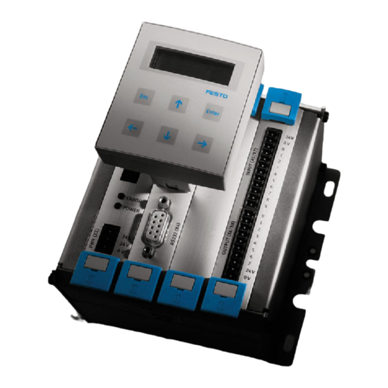
- Page 1 Smart Positioning Controller SPC200 Kurz- beschreibung Short description Feldbus- Baugruppe SPC200-COM-CAN Field bus module type SPC200-COM-CAN – Deutsch – English – Español – Français – Italiano – Svenska 396 537 0012NH...
- Page 2 ......... . . Edition: 0012NH Original: de © (Festo AG & Co., D-73726 Esslingen, Germany, 2000) Internet: http://www.festo.com E-Mail: service_international@festo.com...
- Page 3 Aktoren können ungewollt aktiviert und der SPC200 beschädigt werden, wenn Baugruppen bei eingeschal- teter Spannungsversorgung hinzugefügt oder entfernt werden. Schalten Sie vor Installations- und Wartungs- arbeiten folgende Energiequellen in folgender Reihen- folge ab: 1. Druckluftversorgung 2. Lastversorgung und Betriebsspannungsversorgung des SPC200. Festo SPC200-COM-CAN 0012NH Deutsch...
- Page 4 Es darf nur eine Feldbus-Baugruppe instal- liert werden. Alle E/As installierter E/A-Baugruppen sind frei programmierbar. Baugruppen ausbauen 1. Druckluftversorgung und Betriebsspannung abschal- ten. 2. Anschlusskabel auf der Baugruppenfront lösen und abziehen. 3. Beide Sicherungshebel durch Verschieben entriegeln (siehe folgendes Bild). Festo SPC200-COM-CAN 0012NH Deutsch...
- Page 5 4. Baugruppe an der Frontplatte fassen und hinaus- ziehen. 5. Ggf. freibleibende Steckplätze mit Blindplatten verschließen. Richtung zum Entriegeln Frontplatte der Baugruppe Verriegelt selbsttätig Messerleiste Sicherungshebel Führungsschiene Festo SPC200-COM-CAN 0012NH Deutsch...
- Page 6 Bauteile auf der Leiterplatte beschädigt werden. 4. Achten Sie darauf, dass die Stecker der Messerleisten richtig aufeinander liegen. Schieben Sie die Bau- gruppe dann mit leichtem Druck vollständig ein. Daraufhin verriegeln die Sicherungshebel selbsttätig (siehe Bild). Festo SPC200-COM-CAN 0012NH Deutsch...
-
Page 7: Installation
Verwenden Sie als Feldbusleitung eine verdrillte, ge- schirmte 4-Drahtleitung. Über die Feldbusleitung wird die Busschnittstelle und die interne Logik der Feldbus-Bau- gruppe versorgt. Pin-Belegung Beschreibung 0 V-Busschnittstelle/Logik (CAN_GND) Data - (CAN_L) Schirm (CAN_SHLD) Data + (CAN_H) DC + 24 V-Busschnittstelle/Logik (CAN_V+) Festo SPC200-COM-CAN 0012NH Deutsch... - Page 8 Adern Data + (Pin 4) und Data - (Pin 2) des Feldbussteckers ein Abschlusswiderstand (120 Ohm, 0,25 Watt) zu installieren. Verwenden Sie T-Adapter, so emp- fiehlt es sich, den Abschlusswiderstand am freien Ausgang des T-Adapters zu installieren. Festo SPC200-COM-CAN 0012NH Deutsch...
- Page 9 Für frei programmierbare Eingänge (Optional) Q10.0...Q10.15 Für Steuersignale und frei prog. für Ausgänge Q11.0...Q13.15 frei programmierbare Ausgänge (Optional) Satzselektion I10.0...I10.15 Für Steuersignale I11.0, I11.1 und Für Satznummer I11.8...I11.15 Q10.0...Q10.15 Für Steuersignale *) Adressangaben aus Sicht des SPC200 Festo SPC200-COM-CAN 0012NH Deutsch...
- Page 10 Der SPC200 ist bereit zum grün Datenaustausch und ist digen. Scan-Liste des online am Bus. Es findet je- entsprechenden Masters doch keine Kommunika- überprüfen/korrigieren. tionsverbindung zu einem Master statt. Möglicher- weise ist der SPC200 noch keinem Master zugeordnet. Festo SPC200-COM-CAN 0012NH Deutsch...
- Page 11 Master auf Kommunika- – SPC200 wurde über einen tionsfähigkeit prüfen. S Time-Out Zustand des längeren Zeitraum (Time- Out-Zeit) nicht mehr SPC200 zurücksetzen angesprochen durch neues Allokieren. SPC200 an den Bus neu zuschalten. Festo SPC200-COM-CAN 0012NH Deutsch...
-
Page 12: Technische Daten
Schwingung und Schock – Schwingung geprüft nach DIN/IEC 68 Teil 2–6 Schärfegrad 1 – Schock geprüft nach DIN/IEC 68 Teil 2–27 Schärfegrad 2 1) Mit einer Einzelgenehmigung auch einsetzbar im Wohnbereich (Wohn-, Geschäfts- und Gewerbebereich, Kleinbetriebe). Festo SPC200-COM-CAN 0012NH Deutsch... - Page 13 Before undertaking installation and/or maintenance work, switch off the following sources of power in the se- quence specified: 1. The compressed air supply 2. The load voltage and operating voltage for the SPC200. Festo SPC200-COM-CAN 0012NH English...
- Page 14 Removing the modules 1. Switch off the compressed air supply and operating voltage. 2. Disconnect and remove the connecting cable on the front of the module. 3. Unlock both locking levers by pushing them (see fol- lowing diagram). Festo SPC200-COM-CAN 0012NH English...
- Page 15 4. Hold the module on the front plate and pull it out. 5. If applicable, seal unused locations with blank plates. Direction for unlocking Front plate of module Locks automatically Multi connector strip Locking lever Guide rail Festo SPC200-COM-CAN 0012NH English...
- Page 16 4. Make sure that the plugs of the multi connector strip are inserted correctly. Then gently press in the module completely. The locking levers will then lock automati- cally (see diagram). Festo SPC200-COM-CAN 0012NH English...
- Page 17 Pin assignment User manual 0 V bus interface/logic (CAN_GND) Data - (CAN_L) Screening/shield (CAN_SHLD) Data + (CAN_H) +24 V DC bus interface/logic (CAN_V+) Festo SPC200-COM-CAN 0012NH English...
- Page 18 (120 Ohm, 0.25 Watt) must be fitted between the cores Data + (pin 4) and Data - (pin 2) of the field bus plug. If you are using T-adapters, we recommend that you fit the terminating resistor on the unused output of the T-adapter. Festo SPC200-COM-CAN 0012NH English...
-
Page 19: Instructions On Commissioning
For control signals and freely pro- grammable outputs Q11.0...Q13.15 Freely programmable outputs (op- tional) Record I10.0...I10.15 For control signals selection I11.0, I11.1 and For record number I11.8...I11.15 Q10.0...Q10.15 For control signals *) Address specification as seen by the SPC200 Festo SPC200-COM-CAN 0012NH English... - Page 20 Check/correct the on the bus. But there is no scan list of the appropri- communication connection ate master. to a master. The SPC200 is probably not yet assigned to a master. Festo SPC200-COM-CAN 0012NH English...
- Page 21 Check communication-time-out master for communica- – SPC200 has not been ad- tion ability S Reset time-out status of dressed for a long period (time-out time) SPC200 and allocate new status. Switch SPC200 onto the bus again Festo SPC200-COM-CAN 0012NH English...
-
Page 22: Technical Specifications
Tested as per DIN/IEC 68 part 2-6 Severity 1 – Shock Tested as per DIN/IEC 68 part 2-27 severity class 2 1) With individual authorization can be used in residential areas (living, business and commercial areas, small firms). Festo SPC200-COM-CAN 0012NH English... - Page 23 Antes de realizar trabajos de mantenimiento y/o instalación, desconectar las siguientes fuentes de potencia en la secuencia especificada. 1. la alimentación de aire comprimido 2. la tensión de carga y la tensión de funcionamiento del SPC200. Festo SPC200-COM-CAN 0012NH Español...
- Page 24 1. Desconectar el aire comprimido y la tensión de alimen- tación. 2. Desconectar y retirar el cable de conexión en la parte frontal del módulo. 3. Desbloquear ambas palancas de bloqueo empujándo- las (véase la figura siguiente). Festo SPC200-COM-CAN 0012NH Español...
- Page 25 4. Sostener el módulo por la placa frontal y tirar de él. 5. Si es aplicable, tapar las posiciones no utilizadas con placas ciegas. Sentido para el desbloqueo Placa frontal del módulo Se bloquea automática- Multiconector mente Raíl de guía Palanca de bloqueo Festo SPC200-COM-CAN 0012NH Español...
- Page 26 4. Asegurarse de que las clavijas del multiconector se insertan correctamente. A continuación introducir el módulo completamente. Las palancas de bloqueo se cerrarán automáticamente (véase figura). Festo SPC200-COM-CAN 0012NH Español...
-
Page 27: Instalación
Asignación de pines Conexión asignada 0 V interface del bus/lógica (CAN_GND) Data - (CAN_L) Apantallamiento (CAN_SHLD) Data + (CAN_H) +24 V DC interface del bus/lógica (CAN_V+) Festo SPC200-COM-CAN 0012NH Español... - Page 28 Data + (pin 4) y Data - (pin 2) en la clavija del bus de campo. Si utiliza adaptadores en T, recomenda- mos montar la resistencia terminal en la salida sin utilizar el adaptador en T. Festo SPC200-COM-CAN 0012NH Español...
- Page 29 Salidas libremente programables (opcional) Selección de I10.0...I10.15 Para señales de control registro I11.0, I11.1 y Para el número de registro I11.8...I11.15 Q10,0...Q10,15 Para señales de control *) Especificación de la dirección como se ha visto para SPC200 Festo SPC200-COM-CAN 0012NH Español...
- Page 30 Comprobar/corregir verde online en el bus. Pero no hay la lista de scan del corres- comunicación con el master. pondiente master. El SPC200 probablemente no esté aún asignado a un master. Festo SPC200-COM-CAN 0012NH Español...
- Page 31 S Restablecer el estado de – El SPC200 no ha sido di- reccionado durante un time-out del SPC200 y largo período (tiempo asignar nuevo estado. desbordado/time-out) Conectar el SPC200 de nuevo en el bus Festo SPC200-COM-CAN 0012NH Español...
-
Page 32: Especificaciones Técnicas
Verificada según DIN/IEC 68 parte 2-6 severidad 1 – Choque Verificada según DIN/IEC 68 parte 2-27 severidad clase 2 1) Con autorización individual puede utilizarse en zonas residenciales (viviendas, zonas comerciales y de negocio, pequeñas empresas). Festo SPC200-COM-CAN 0012NH Español... -
Page 33: Instructions D'utilisation
Avant l’installation ou tous travaux d’entretien, couper les sources d’énergie sui- vantes dans l’ordre suivant : 1. l’alimentation en air comprimé 2. l’alimentation principale et l’alimentation du SPC200. Festo SPC200-COM-CAN 0012NH Français... - Page 34 Démontage des cartes 1. Couper l’alimentation en air comprimé et l’alimenta- tion électrique. 2. Débrancher le câble de connexion à l’avant de la carte. 3. Déverrouiller les deux leviers de blocage en les pous- sant (voir figure suivante). Festo SPC200-COM-CAN 0012NH Français...
- Page 35 4. Saisir la carte par la face avant et la retirer. 5. Le cas échéant, fermer les emplacements libres à l’aide de plaques d’obturation. Sens de déverrouillage Face avant de la carte Verrouillage automatique Connecteur Levier de blocage Rail de guidage Festo SPC200-COM-CAN 0012NH Français...
- Page 36 4. Veiller à ce que les contacts des connecteurs soient bien positionnés l’un sur l’autre. Enfoncer complète- ment la carte en appliquant une légère pression. En- suite, les leviers de blocage se verrouillent automati- quement (voir figure). Festo SPC200-COM-CAN 0012NH Français...
-
Page 37: Installation
Affectation des broches Broche Description Interface de bus/logique 0 V (CAN_GND) Données - (CAN_L) Blindage (CAN_SHLD) Données + (CAN_H) Interface de bus/logique + 24 V CC (CAN_V+) Festo SPC200-COM-CAN 0012NH Français... - Page 38 Données + (broche 4) et Données – (broche 2) du connecteur de bus de terrain. En cas d’utilisation d’un adap- tateur en T, il est recommandé d’installer la résistance de terminaison à la sortie libre de cet adaptateur. Festo SPC200-COM-CAN 0012NH Français...
-
Page 39: Instructions De Mise En Service
Pour les sorties programmables (option) Sélection de E10.0...E10.15 Pour les signaux de commande commande E11.0, I11.1 et Pour le numéro de bloc E11.8...E11.15 Q10.0...Q10.15 Pour les signaux de commande *) Adresses indiquées à partir du SPC200 Festo SPC200-COM-CAN 0012NH Français... - Page 40 Vérifier / corriger la liste clignote ligne avec le bus. Cepen- Scan du maître corres- dant, aucune communica- pondant. tion n’est établie avec un maître. Il est possible que le SPC200 ne soit pas encore affecté à un maître. Festo SPC200-COM-CAN 0012NH Français...
- Page 41 – Le SPC200 n’a plus été maître. S Réinitialiser le Timeout du appelé pendant un laps de temps trop long SPC200 en effectuant une (Timeout écoulé). nouvelle allocation. Brancher à nouveau le SPC200 sur le bus. Festo SPC200-COM-CAN 0012NH Français...
-
Page 42: Caractéristiques Techniques
2-6 Niveau de sévérité 1 – Chocs Contrôlée selon DIN / CEI 68 partie 2-27 Niveau de sévérité 2 1) Peut également être utilisé sous autorisation particulière dans des locaux d’habitation (logements, commerces ou petites entreprises). Festo SPC200-COM-CAN 0012NH Français... - Page 43 Prima di effettuare lavori di installazione e manutenzione, scol- legare le seguenti fonti di energia nell’ordine indicato: 1. aria compressa 2. tensione di carico e alimentazione della tensione di esercizio all’SPC200. Festo SPC200-COM-CAN 0012NH Italiano...
- Page 44 1. Scollegare l’alimentazione di aria compressa e della tensione di esercizio. 2. Allentare e disinserire il cavo di collegamento dalla parte anteriore del modulo. 3. Spostare e sbloccare le due levette di bloccaggio (vedi figura successiva). Festo SPC200-COM-CAN 0012NH Italiano...
- Page 45 4. Prendere il modulo dalla parte frontale ed estrarlo. 5. Chiudere gli slot eventualmente liberi con le apposite piastre cieche. Sbloccaggio del modulo Piastra frontale del modulo Bloccaggio automatico Lamina Levetta di bloccaggio Profilo guida Festo SPC200-COM-CAN 0012NH Italiano...
- Page 46 4. Accertarsi che i connettori maschio delle lamine siano sovrapposti correttamente. Inserire il modulo fino in fondo esercitando una leggera pressione. Le levette di bloccaggio scattano automaticamente bloccandolo in posizione (vedi figura). Festo SPC200-COM-CAN 0012NH Italiano...
-
Page 47: Installazione
Il cavo Fieldbus assicura l’alimentazione elet- trica all’interfaccia bus e alla logica interna del modulo Fieldbus. Occupazione dei pin Descrizione 0 V- interfaccia bus/gruppo logico (CAN_GND) Data - (CAN_L) Schermo (CAN_SHLD) Data + (CAN_H) + 24 VCC -interfaccia bus/gruppo logico (CAN_V+) Festo SPC200-COM-CAN 0012NH Italiano... - Page 48 Fieldbus, installare una resistenza terminale (120 Ohm, 0,25 Watt) tra i conduttori Data + (Pin 4) e Data - (Pin 2). In caso di impiego di adattatori a T si consiglia di installare la resistenza terminale sull’uscita libera dell’adattatore. Festo SPC200-COM-CAN 0012NH Italiano...
- Page 49 Per impulsi di comando e programmabili per uscite Q11.0...Q13.15 Uscite programmabili (optional) Selezione record I10.0...I10.15 Per impulsi di comando I11.0, I11.1 e Per numero di record I11.8...I11.15 Q10.0...Q10.15 Per impulsi di comando *) Indirizzi in base all’SPC200. Festo SPC200-COM-CAN 0012NH Italiano...
- Page 50 Verificare ed even- verde con il bus. Tuttavia non av- tualmente correggere la viene alcuna comunicazione scan-list del Master inte- con un Master. È possibile ressato. che l’SPC200 non sia ancora stato assegnato a un Master. Festo SPC200-COM-CAN 0012NH Italiano...
- Page 51 Master sia zione. predisposto per la comu- – L’SPC200 non è stato uti- nicazione. S Resettare il time-out lizzato per lungo tempo (periodo di Time-Out) dell’SPC200 mediante riallocazione. Ricollegare l’SPC200 al bus. Festo SPC200-COM-CAN 0012NH Italiano...
-
Page 52: Dati Tecnici
Parte 2-6 classe di precisione 1 – Urti Misurata a norma DIN/IEC 68 Parte 2-27 classe di precisione 2 1) È possibile utilizzare l’SPC200 anche in ambienti non industriali previa autorizzazione (abitazioni, locali commerciali, uffici, piccole aziende). Festo SPC200-COM-CAN 0012NH Italiano... - Page 53 Aktorer kan oönskat aktiveras och SPC200 kan skadas, om komponenter tillfogas eller avlägsnas vid tillkopp- lad spänningsförsörjning. Innan installations- och un- derhållsarbeten påbörjas skall följande energikällor frånkopplas i angiven ordningsföljd: 1. Tryckluftsförsörjning 2. Lastförsörjning och driftspänningsförsörjning av SPC200. Festo SPC200-COM-CAN 0012NH Svenska...
- Page 54 Alla I/O:s på installerade I/O-kompo- nenter kan programmeras fritt. Demontera komponenter 1. Frånkoppla tryckluftsförsörjning och spänningsmat- ning. 2. Lossa och avlägsna anslutningskablar på komponen- tens framsida. 3. Öppna båda säkerhetsspakar genom att skjuta på dem (se följande bild). Festo SPC200-COM-CAN 0012NH Svenska...
- Page 55 4. Fatta komponenten på frontplattan och dra ut den. 5. Tillslut om så erfordras tomma kontakter med blind- plattor. Riktning för att öppna Komponentens frontplatta Låses automatiskt Multipol Säkerhetsspak Styrskena Festo SPC200-COM-CAN 0012NH Svenska...
- Page 56 4. Se till att multipolernas stickkontakter ligger riktigt på varandra. Skjut sedan in komponenten komplett med ett lätt tryck. Därpå låser sig säkerhetsspakarna auto- matiskt (se bild). Festo SPC200-COM-CAN 0012NH Svenska...
- Page 57 Använd en partvinnad, skärmad 4-trådskabel som fältbus- sanslutning. Via fältbussledningen försörjs fältbusskom- ponentens bussgränssnitt och interna logik. Stiftbeläggning Stift Beskrivning 0 V bussgränssnitt/logik (CAN_GND) Data - (CAN_L) Skärm (CAN_SHLD) Data + (CAN_H) DC + 24 V bussgränssnitt/logik (CAN_V+) Festo SPC200-COM-CAN 0012NH Svenska...
- Page 58 Befinner sig SPC200 vid fältbussens ände, ska ett termi- neringsmotstånd (120 ohm, 0,25 watt) installeras mellan fältbusskontaktens ledare Data + (stift 4) och Data - (stift 2). Om en T-adapter används rekommenderas att terminer- ingsmotstånd installeras på T-adapterns fria kontaktända. Festo SPC200-COM-CAN 0012NH Svenska...
- Page 59 För fritt programmerbara ingångar (tillval) Q10.0...Q10.15 För styrsignaler och fritt prog. utgångar Q11.0...Q13.15 Fritt programmerbar ra utgångar (tillval) Satselektion I10.0...I10.15 För styrsignaler I11.0, I11.1 och För satsnummer I11.8...I11.15 Q10.0...Q10.15 För styrsignaler *) Adressangivelser utgående från SPC200 Festo SPC200-COM-CAN 0012NH Svenska...
- Page 60 SPC200 är redo för data- grönt överföring och är online med Kontrollera/korrigera bussen. Det finns däremot skannerlistan för den ingen kommunikationsför- aktuella mastern. bindelse till en master. Even- tuellt har SPC200 ännu inte tilldelats en master. Festo SPC200-COM-CAN 0012NH Svenska...
- Page 61 Kontrollera mas- rat kommunikations- tern beträffande kommu- Time-Out. nikationsförmåga. S Återställ timeout av – SPC200 har under en längre tid (Time-Out-tid) SPC200 genom ny allo- inte tagit emot någon kering. Starta om SPC200 signal. på bussen. Festo SPC200-COM-CAN 0012NH Svenska...
-
Page 62: Tekniska Data
Vibrationer och stötar – Vibrationer Kontrollerad enligt DIN/IEC 68 del 2-6 intensitetsgrad 1 – Stötar Kontrollerad enligt DIN/IEC 68 del 2-27, intensitetsgrad 2 1) Får med särskilt tillstånd användas även i boendemiljö (bostäder, kontor, butiker och småindustri). Festo SPC200-COM-CAN 0012NH Svenska...
Need help?
Do you have a question about the SPC200 Series and is the answer not in the manual?
Questions and answers