Table of Contents
Advertisement
Quick Links
Via M.E.Lepido,182 - 40132 Bologna, Italy
ASSEMBLY AND USE
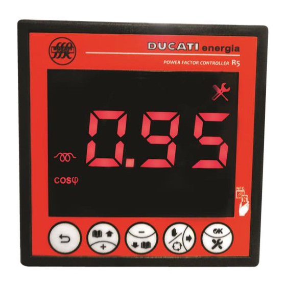
R5 POWER FACTOR
The new DUCATI energia R5 is a power factor controller designed to allow a simple and quick installation as well as a
correct start of a power factor correction equipment. It is suitable to many applications relating to single-phase and three-
phase networks, with or without power generation systems. The R5 models technology allows exchanging system
performance and status data both on site - through a Smartphone App - and remotely, for monitoring purposes, through
Ducati energia datalogger devices.
o 5-step power factor automatic controller.
o Display with backlit icons with red LEDs, clearly readable from a distance, 5 navigation keys for functions and
settings.
o 868MHz Radio, NFC and RS485 connectivity options.
o Voltage measurement accuracy: 0.2%%±0.5 digit.
o Current measurement accuracy: 1%%±0.5 digit.
o
Alarms can be completely defined by the user and associated to relay outputs.
Version D - February 2018
FW reference version: V 0.91 and higher
MU-MID-R5-D-ENG.doc
info@ducatienergia.com
INSTRUCTIONS
CONTROLLERS
GENERAL DESCRIPTION
MAIN FEATURES
+39 051-6411511
www.ducatienergia.com
+39 051-402040
Page1 of 70
Advertisement
Chapters
Table of Contents

Related Manuals for Ducati R5


Summary of Contents for Ducati R5
- Page 1 GENERAL DESCRIPTION The new DUCATI energia R5 is a power factor controller designed to allow a simple and quick installation as well as a correct start of a power factor correction equipment. It is suitable to many applications relating to single-phase and three- phase networks, with or without power generation systems.
-
Page 2: Table Of Contents
CONTENTS R5 MODELS ................................... 4 WARNINGS .................................... 4 TECHNICAL FEATURES ..............................5 INSTALLATION ..................................6 CONNECTIONS ..................................7 ................................. 7 ASIC ONNECTIONS 5.1.1 Three-phase network without standard neutral with 400V phase-phase voltage ............7 5.1.2 Three-phase network without neutral in cogeneration with 400V phase-phase voltage ........... 8 5.1.3... - Page 3 RS485 serial connection ............................62 8.7.2 868Mhz Radio Interface ............................62 8.7.3 NFC ..................................62 ......................... 63 ANUAL POWER FACTOR CORRECTION MODE ..........................64 RESENCE OF BLOCKING REACTORS 8.10 ................................65 IRMWARE UPDATE APPENDIX - MENU NAVIGATION ..........................66 MU-MID-R5-D-ENG.doc Page3 of 70...
-
Page 4: R5 Model
2 WARNINGS Carefully read this guide before using the power factor controller The purpose of this guide is to provide the information to install and start using the models of the range of R5 power factor controllers. The device must be installed and wired by qualified personnel. -
Page 5: Technical Features
Termination resistance: 120Ohm integrated (activated with external jumper) 13.56Mhz NFC interface: – o Data exchange with Smartphone through the antenna located behind the display use Android app Ducati Smart Energy. https://play.google.com/store/apps/details?id=it.ducatienergia.smartenergy 868Mhz Radio interface: o Carrier frequency: 868MHz –... -
Page 6: Installation
4 supplied retaining clips, letting them slide fully home against panel rear wall. Dimensions +0.8mm -0mm 92.0mm Dimensions +0.8mm -0mm 92.0mm Chap. 5 - CONNECTIONS For flying connector wiring, refer to CONTENTS GO BACK TO MU-MID-R5-D-ENG.doc Page6 of 70... -
Page 7: Connections
5.1 Basic Connections 5.1.1 Three-phase network without standard neutral with 400V phase-phase voltage Connect the R5 controller as indicated in the figure below. NOTE: the diagram shows a FF1 configuration, for FF2 and FF3 configurations, refer to the complete operating manual, available at the following link: https://www.ducatienergia.com/product.php?lang=en&id=8&cat=13&product=89... -
Page 8: Three-Phase Network Without Neutral In Cogeneration With 400V Phase-Phase Voltage
5.1.2 Three-phase network without neutral in cogeneration with 400V phase-phase voltage Connect the R5 controller as indicated in the figure below. NOTE: the diagram shows a FF1 configuration, for FF2 and FF3 configurations, refer to the complete operating manual, available at the following link: https://www.ducatienergia.com/product.php?lang=en&id=8&cat=13&product=89... -
Page 9: Other Basic Connections
- Three-phase without neutral in co-generation with phase-neutral voltage at 230Vac, with or without VT. For this type of connections, refer to the complete operating manual, available at the following link: https://www.ducatienergia.com/product.php?lang=en&id=8&cat=13&product=89 CONNECTIONS GO BACK TO CONTENTS GO BACK TO MU-MID-R5-D-ENG.doc Page9 of 70... -
Page 10: Rs485 Serial Connection
The power supply unit (PWR) and the reading electronics (LOAD) must comply with the indications provided in the Chap. 3 - TECHNICAL FEATURES technical features of relay outputs in CONNECTIONS GO BACK TO CONTENTS GO BACK TO MU-MID-R5-D-ENG.doc Page10 of 70... -
Page 11: Hardware Configuration Auto-Acquisition And Commissioning
1.) At first system power-up or at power-up after a restart forced by the reset procedure, the R5 Controller performs an automatic insertion of capacitor banks to check the connections and the amount of bank power. - Page 12 Should the controller not be able to automatically define the type of configuration due to unfavourable load Chap. 7.1.3 conditions, it will show the setting screen of parameter Current reading phase that will have to be manually entered (or confirmed). Fig.4a Fig.4b MU-MID-R5-D-ENG.doc Page12 of 70...
- Page 13 Any generation plants present can be turned on; in this case set the Cogeneration parameter = from the Setup Chap. 7 - SETTINGS Menu HARDWARE CONFIGURATION AUTO-ACQUISITION AND COMMISSIONING GO BACK TO CONTENTS GO BACK TO MU-MID-R5-D-ENG.doc Page13 of 70...
-
Page 14: R Educed Auto - Acquisition
Auto-acquisition reset procedure has just been performed 1.) At first system power-up or at power-up after a restart forced by the reset procedure, the R5 Controller performs an automatic insertion of capacitor banks to check the connections and the amount of bank power. - Page 15 Any generation plants present can be turned on; in this case set the Cogeneration parameter = from the Setup Chap. 7 - SETTINGS Menu HARDWARE CONFIGURATION AUTO-ACQUISITION AND COMMISSIONING GO BACK TO CONTENTS GO BACK TO MU-MID-R5-D-ENG.doc Page15 of 70...
-
Page 16: Settings
Chap. 7.5 - Alarm settings GO TO Chap. 7.6 - Advanced settings GO TO Chap. 7.7 - Parameter default range and values GO TO Chap. 7.8 - Numerical value entering modes GO TO CONTENTS GO BACK TO MU-MID-R5-D-ENG.doc Page16 of 70... -
Page 17: C Onnection Settings
After parameter is confirmed, the controller will move to the next parameter setting screen (Reversal towards CT). 7.1.4 Reversal towards CT The default value is "OFF". The possible permitted values for the parameter are [ON; OFF]. MU-MID-R5-D-ENG.doc Page17 of 70... -
Page 18: Cogeneration
Power Factor Controller (400 or 230). Example 2: if the used VT Primary winding is equal to 100000A, set: If a permitted value is entered, the controller will move to the next parameter setting screen (VT secondary winding). MU-MID-R5-D-ENG.doc Page18 of 70... -
Page 19: Vt Secondary Winding
Example 2: If the power supply (or VT) was connected between the R phase and the neutral, select the value After parameter is confirmed, the controller will move to the next parameter setting screen (Capacitor nominal voltage). SETTINGS GO BACK TO CONTENTS GO BACK TO MU-MID-R5-D-ENG.doc Page19 of 70... -
Page 20: E Quipment Settings
Example 2: if the voltage is 4000V, set (for the numerical value entering modes, refer to entering modes If the controller is installed on a Ducati energia power factor correction equipment, the value to be entered is the one specified on equipment plate. -
Page 21: Re-Connection Time
The default value is "CAP". The possible permitted values for the parameter are [CAP; OFF; ON; ALA]. Select the "CAP" value for an output connected to a capacitor bank that you want to be automatically piloted by the controller. MU-MID-R5-D-ENG.doc Page21 of 70... -
Page 22: Step N Power (N=1,2,3,4,5)
Example: to set 1kVar, enter (for numerical value entering mode refer to modes If the controller is installed on a Ducati energia power factor correction equipment, the value to be entered is the one specified on equipment plate. If a permitted value is entered, the controller will move to the setting screen of parameter Step n+1 function (refer to Chap. -
Page 23: Alarm N (N=1,2,3,4,5)
“ ” Select the THD%V value to associate the relay output n to the high THDV% alarm (for Chap. 7.5.9 - THDV alarm threshold Chap.7.5.10 - THDV alarm delay further details refer to MU-MID-R5-D-ENG.doc Page23 of 70... - Page 24 After parameter is confirmed, the controller will move to the next parameter setting screen Step n+1 function (refer Chap. 7.2.5 - Step n function (n=1,2,3,4,5) SETTINGS GO BACK TO CONTENTS GO BACK TO MU-MID-R5-D-ENG.doc Page24 of 70...
-
Page 25: P Ower Factor Correction Settings
NOTE: average values are only available via the communication interfaces RS485 and Radio 868MHz for the provided models. If a permitted value is entered, the controller will move to the next parameter setting screen (Protocol). SETTINGS GO BACK TO CONTENTS GO BACK TO MU-MID-R5-D-ENG.doc Page25 of 70... -
Page 26: C Ommunication Interface Settings
NOTE 2: the value "115k" corresponds to a baudrate of 115.2kbps. After parameter is confirmed, the controller will move to the next parameter setting screen (Overvoltage alarm threshold). SETTINGS GO BACK TO CONTENTS GO BACK TO MU-MID-R5-D-ENG.doc Page26 of 70... -
Page 27: A Larm Settings
The default value is "5.50". The possible permitted values for the parameter will range from 90% to 120% of the value set for parameter CT primary winding with a 1% resolution. To disable the alarm select the "OFF" value. MU-MID-R5-D-ENG.doc Page27 of 70... -
Page 28: Overcurrent Alarm Delay
408; 404; 400; 396; 392; 388; 384; 380; 376; 372; 368; 364; 360; OFF]. “ ” Example 2: if VT primary winding = 5.00k and you wish to set the threshold at 95% (4.75kV), scroll the suggested values and set: MU-MID-R5-D-ENG.doc Page28 of 70... -
Page 29: Low Voltage Alarm Delay
NOTE: the alarm will be activated and deactivated if the reference measurement steadily stays above or under the threshold for the time set. If a permitted value is entered, the controller will move to the next parameter setting screen (THDV alarm threshold). MU-MID-R5-D-ENG.doc Page29 of 70... -
Page 30: Thdv Alarm Threshold
The default value is "999". The permitted range for the parameter is [1%÷100%]. To disable the alarm enter value "999" Example 1: to set the threshold at 10%, enter: If a permitted value is entered, the controller will move to the next parameter setting screen (THDI alarm delay). MU-MID-R5-D-ENG.doc Page30 of 70... -
Page 31: Thdi Alarm Delay
NOTE: the alarm will be activated and deactivated if the reference measurement steadily stays above or under the threshold for the time set. If a permitted value is entered, the controller will move to the next parameter setting screen (Reset). SETTINGS GO BACK TO CONTENTS GO BACK TO MU-MID-R5-D-ENG.doc Page31 of 70... -
Page 32: A Dvanced Settings
7.6 Advanced settings WARNING: if not expressly requested by this manual, the following parameters must be edited only by qualified staff and/or according to the indications provided by Ducati Energia technicians. To access the Advanced Parameter Menu press keys at the same time for at least 10sec. - Page 33 Power threshold for auto-acquisition secondary windings) Chap. 7.6 – P.16 P.16 868MHz radio address – Chap. 7.6 P.17 P.17 868MHz radio channel Chap. 7.6 – P.18 P.18 868MHz radio power – Chap. 7.6 3PH/1PH P.19 P.19 Type of network MU-MID-R5-D-ENG.doc Page33 of 70...
- Page 34 Power factor correction failed alarm Chap. 7.6 P.23 delay (on CT Chap. 7.6 – 0.03 P.24 P.24 THDI invalidation threshold secondary winding) – Chap. 7.6 0/1/2/3 P.25 P.25 Alarm masking management SETTINGS GO BACK TO CONTENTS GO BACK TO MU-MID-R5-D-ENG.doc Page34 of 70...
-
Page 35: N Umerical Value Entering Modes
In the fourth case, move to the position of the third digit from the left (red arrow) and increase it by using key until the thousands icon ( ) appears, then adjust the remaining digits by taking into account that the resolution will be in the thousands. SETTINGS GO BACK TO CONTENTS GO BACK TO MU-MID-R5-D-ENG.doc Page35 of 70... -
Page 36: Using The Controller
8.1 Controller information 8.1.1 Model and Serial Number The information relating to model (with relevant Part Number) and Serial Number of the R5 Controller can be inferred from the silver plate affixed on enclosure right side. The same information can be also inferred from the RS485, Radio 868MHz communication interfaces and through Chap. -
Page 37: D Isplay And Key Description
Cogeneration mode (4-Quadrants) active or Cogeneration parameter. (If flashing) RS485/Radio 868MHz communication in progress. CT and VT Transformer parameters. Measurement unit. Cosphi measurement or parameter. THD% measurement or parameter. MU-MID-R5-D-ENG.doc Page37 of 70... -
Page 38: Key Functions
8.2.2 Key functions The function associated to keys depends on the context in which they are pressed. The following tables describe key functions in the various menus available on R5 Controller. – KEY FUNCTIONS MEASUREMENT MENU Short press Long press... -
Page 39: M Easurement Menu
The next page relates to the reactive power, which is recognisable by the measurement unit in [VAr]. The next page relates to the current, which is recognisable by the measurement unit in [A]. The next page relates to the voltage, which is recognisable by the measurement unit in [V]. MU-MID-R5-D-ENG.doc Page39 of 70... - Page 40 NOTE: For the values of reactive power, active power and apparent power, if the measured value is equal to one MVAr, one MW and one MVA respectively, the following screen will be respectively displayed alternately with the numerical value. USING THE CONTROLLER GO BACK TO CONTENTS GO BACK TO MU-MID-R5-D-ENG.doc Page40 of 70...
-
Page 41: S Tatistics Menu
The next displayed page relates to the number of operating hours h of the first capacitor bank. The following screen will appear: that will be alternately shown with the numerical value. The next 4 pages show the number of operating hours of banks from 2 to 5. MU-MID-R5-D-ENG.doc Page41 of 70... -
Page 42: Alarm Statistics
Chap. 7.5.5 - Low voltage alarm threshold Chap. 7.5.6 - Low voltage alarm delay For alarm settings, refer to The next displayed page relates to the low current alarm. The following screen will appear: MU-MID-R5-D-ENG.doc Page42 of 70... -
Page 43: Power Factor Overcorrection Alarm Delay Min
Chap. 7.3.2 - Cosphi setpoint tolerance For alarm settings, refer to and to parameter – Chap. 7.6 P.22 Power factor overcorrection alarm delay ( The next displayed page relates to the power factor correction failed alarm. The following screen will appear: MU-MID-R5-D-ENG.doc Page43 of 70... - Page 44 For alarm settings, refer to P.20 Micro-interruption duration ( To quit the Statistics Menu and go back to the Measurement Menu press key for more than 2sec. USING THE CONTROLLER GO BACK TO CONTENTS GO BACK TO MU-MID-R5-D-ENG.doc Page44 of 70...
-
Page 45: A Larm Management And Display
The next displayed page relates to the low current alarm that will be alternately shown with the numerical value corresponding to the minimum current value measured since alarm activation (0A in the example shown). MU-MID-R5-D-ENG.doc Page45 of 70... - Page 46 ). For further information on alarm management, refer to Chap. 8.5.2.9 - Power factor correction failed alarm The next displayed page relates to the micro-interruption alarm on the network voltage that will not be alternately shown with any numerical value. MU-MID-R5-D-ENG.doc Page46 of 70...
- Page 47 2sec. The cosphi value and the alarm icon will be displayed on the top left. The alarm will be anyway active in the Current Alarm Menu. USING THE CONTROLLER GO BACK TO CONTENTS GO BACK TO MU-MID-R5-D-ENG.doc Page47 of 70...
-
Page 48: Alarm Masking Management
8.5.2 Alarm description 8.5.2.1 Overvoltage alarm ACTIVATION The overvoltage alarm is activated if the voltage reading of the R5 Controller is above the value defined by Chap. 7.5.1 parameter Overvoltage alarm threshold for a time (in sec) equal to the value of parameter Overvoltage Chap. -
Page 49: Overcurrent Alarm
8.5.2.2 Overcurrent alarm ACTIVATION The overcurrent alarm is activated if the current reading of the R5 Controller is above the value defined by Chap. 7.5.3 parameter Overvoltage alarm threshold for a time (in sec) equal to the value of parameter Overcurrent Chap. -
Page 50: Low Current Alarm
The low voltage alarm is activated if the voltage reading of the R5 Controller stays under the value defined by Chap. 7.5.5 parameter Low voltage alarm threshold for a time (in sec) equal to the value of parameter Low voltage Chap. - Page 51 The alarm counter will be increased in the Statistics Menu ( ) at every occurrence. DEACTIVATION The alarm is automatically deactivated if the current reading of the R5 Controller stays above the value defined by Chap. 7.5.7 parameter Low current alarm threshold for a time (in sec) equal to the value of parameter Low current Chap.
-
Page 52: Thdi Alarm
(in sec) equal to the value of parameter THDI alarm delay RESET – Alarm can be manually reset from the Current Alarm Menu by pressing key (function possible only if P.13 “ ” Chap. 7.6 Current alarm reset = , refer to 8.5.2.6 THDV alarm ACTIVATION MU-MID-R5-D-ENG.doc Page52 of 70... -
Page 53: Temperature Alarm
, refer to 8.5.2.7 Temperature alarm ACTIVATION The temperature alarm is activated if the temperature value read by the R5 Controller stays above the value defined Chap. 7.5.13 by parameter Temperature alarm threshold for a time (in sec) equal to the value of parameter Chap. -
Page 54: Chap
NOTE: the power factor overcorrection may be caused by: ) = “ON” for an excessive number of batteries; Chap.7.2.5 - setting Step n function ( - incorrect setting of the target cosphi range with respect to the type of load on the system; MU-MID-R5-D-ENG.doc Page54 of 70... -
Page 55: Chap. 7.3.2
- incorrect sizing of the power factor correction equipment with respect to the system load; - presence of degraded or broken batteries; - incorrect setting of the parameters related to the power factor correction, the connections and the equipment in the Setup Menu. MU-MID-R5-D-ENG.doc Page55 of 70... -
Page 56: Chap. 7.3.1
8.5.2.10 Micro-interruption alarm ACTIVATION The micro-interruption alarm is activated if the voltmetric input of the R5 Controller stays below 10% of the nominal Chap. 7.1.8 value defined by parameter VT secondary winding for a time (in msec) equal to the value of parameter P.20 –... -
Page 57: Bank N Breakage Alarm (N=1,2,3,4,5)
Chap. 8.4 The alarm counter will be increased in the Statistics Menu ( ) at each occurrence not causing the complete powering-off of the R5 Controller. DEACTIVATION Chap.7.2.3 The alarm is automatically deactivated after a time equal to the Re-connection time RESET This alarm cannot be manually reset from the Current Alarm Menu. -
Page 58: Maximum Number Of Bank N Insertions (N=1,2,3,4,5) Alarm
) it will nevertheless possible to display the estimated reactive power value of bank n. DEACTIVATION The alarm cannot be deactivated, once a bank is declared as broken, it will not be possible to use it again on the R5 Controller. RESET This alarm cannot be manually reset from the Current Alarm Menu. -
Page 59: Reset Menu
(as a consequence, any Bank n breakage alarm will be reset as well Confirm the reset of the parameter by pressing key for at least 2sec. Chap. 7.2.6 The controller will automatically move to the Setup Menu page relating to parameter Step n power MU-MID-R5-D-ENG.doc Page59 of 70... -
Page 60: Bank N Contactor Switching Manoeuvres Number Reset (N=1,2,3,4,5)
(2kVAr in the example shown). Edit, if necessary, the suggested value. If the controller is installed on a Ducati energia power factor correction equipment, the value to be Chap. 7.8 -... -
Page 61: Auto-Acquisition Reset
” Scroll the suggested values until reaching parameter flashing: The auto-acquisition reset will force a restart of R5 Controller, followed by an automatic check procedure of connection and reactive power of banks, that will be: Chap. 6.1 - Complete auto-acquisition... -
Page 62: C Ommunication Interfaces
For detailed information on configuration parameter settings, refer to P.16 - 868MHz radio address and P.17 - Chap. 7.6 868MHz radio channel. (refer to 8.7.3 NFC The NFC interface is present on all R5 models and its antenna is positioned in the bottom right area of the display of R5 Controller. NFC Antenna position behind the... -
Page 63: M Anual Power Factor Correction Mode
Press keys to scroll the possible values [ON; OFF]. The change in progress can be cancelled by pressing key To confirm, press key MU-MID-R5-D-ENG.doc Page63 of 70... -
Page 64: P Resence Of Blocking Reactors
NOTE: to confirm also in manual mode the status of all outputs as before the activation of manual mode, press key Once sequence is completed, the R5 Controller will move to the cosphi measurement page, signalling that the manual power factor correction mode is active through the dedicated icon coming on:... -
Page 65: F Irmware Update
RS485 serial connection (in the models where available), refer to the protocol document available at the following link: https://www.ducatienergia.com/product.php?lang=en&id=8&cat=13&product=89 for 868Mhz Radio interface (in the models where available), refer to the documents of Ducati Energia Energy Bridge device, available at the following link: www.ducatienergia.com... -
Page 66: Appendix - Menu Navigation
9 APPENDIX - Menu Navigation 1. Navigation among the menus 2. Setting Menu 3. Advanced Setting Menu 4. Measurement Menu 5. Statistics Menu 6. Current Alarm Menu 7. Reset Menu MU-MID-R5-D-ENG.doc Page66 of 70... - Page 67 Chap. 7 MU-MID-R5-D-ENG.doc Page67 of 70...
- Page 68 Chap. 7.6 Chap. 8.3 MU-MID-R5-D-ENG.doc Page68 of 70...
- Page 69 Chap. 8.4 Chap. 8.5.1 MU-MID-R5-D-ENG.doc Page69 of 70...
- Page 70 Chap. 8.6 GO BACK TO CONTENTS MU-MID-R5-D-ENG.doc Page70 of 70...
Need help?
Do you have a question about the R5 and is the answer not in the manual?
Questions and answers