Table of Contents
Advertisement
Quick Links
Download this manual
See also:
User Manual
Advertisement
Table of Contents

Related Manuals for Nibe F2016


Summary of Contents for Nibe F2016
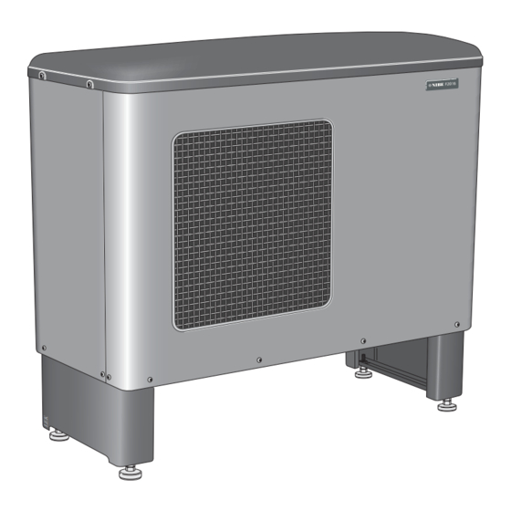
- Page 1 Installer manual NIBE™ F2016 UK 1x230V Air/water heat pump IHB GB 1244-2 031885...
-
Page 3: Table Of Contents
6 Commissioning and adjusting 12 Technical data Preparations Dimensions and setting-out coordinates Filling and venting the heating medium sys- Sound pressure levels Balance temperature Technical specifications Stop temperature Electrical circuit diagram Soft-starter Item register Compressor heater NIBE™ F2016 Table of Contents |... -
Page 4: Important Information
Marking parts. F2016 is CE marked and fulfils IP24. The CE marking means that NIBE ensures that the product meets all regulations that are placed on it based on relev- ant EU directives. The CE mark is obligatory for most Benchmark places responsibilities on both manufacturers products sold in the EU, regardless where they are made. - Page 5 Warranty and insurance information Thank you for installing a new NIBE heat pump in your home. NIBE heat pumps are manufactured in Sweden to the very highest standard so we are pleased to offer our customers a comprehensive guarantee. The product is guaranteed for 24 months for parts and labour from the date of installation or 33 months from the date of manufacture, whichever is the shorter.
- Page 6 Safety breaker Earth circuit-breaker Heating cable type/effect Fuse size, heating cable (F3) Communication cable connected Miscellaneous Condensation water pipe Insulation condensation water pipe, thick- ness (if KVR 10 is not used) Warranty Benchmark checklist Chapter 1 | Important information NIBE™ F2016...
-
Page 7: Delivery And Handling
(see page Care must be exercised so that the heat pump is not scratched during installation. Do not place F2016 directly on the lawn or other non solid surface. NIBE™ F2016... - Page 8 The section of the pipe that can be affected by frost must be heated by the heating cable to prevent freezing. Route the pipe downward from F2016. The outlet of the condensation water pipe must be at a depth that is frost free or alternatively indoors (with reservation for local ordinances and regulations).
- Page 9 The condensation water pipe must have a water trap to prevent air circulation in the pipe. Installation area The distance between F2016 and the house wall must be at least 350 mm. Clearance in front of F2016 should be at least one metre. utrymme Fritt utrymme framför NIBE™...
-
Page 10: Supplied Components
Supplied components 2 flexible hoses (R25) with 4 seals Particle filterR25 Removing the covers Chapter 2 | Delivery and handling NIBE™ F2016... -
Page 11: The Heat Pump Design
3 The heat pump design General NIBE™ F2016 Chapter 3 | The heat pump design... - Page 12 Pipe connections XL 1 Connection, heating medium out of F2016, G1 (Ø28 mm) XL 2 Connection, heating medium in to F2016, G1 (Ø28 mm) XL 20 Service connection, high pressure XL 21 Service connection, low pressure XL 40 Connection, drip tray drain (Ø40 mm) Sensors etc.
-
Page 13: Electrical Cabinets
Terminal block, charge pump, external heating cable Terminal block, thermostat, communication, blocking compressor Terminal block, additional heat, downtime, com- mon alarm Terminal block, 4-way valve Miscellaneous UB 2 Cable gland, incoming supply NIBE™ F2016 Chapter 3 | The heat pump design... -
Page 14: Pipe Connections
NIBE Energy Systems Limited recommends water treat- current norms and directives. ments (supplied by e.g. Fernox and Sentinel) specifically F2016 can only operate up to a return temperature of designed for heat pumps. about 55 °C and an outgoing temperature of about 62 °C Charge pump from the heat pump. -
Page 15: Pressure Drop, Heating Medium Side
Pressure drop, heating medium side F2016 -6, 8, 11 Tryckfall 6 kW 8, 11 kW Flöde 0,10 0,20 0,30 0,40 0,50 0,60 0,70 NIBE™ F2016 Chapter 4 | Pipe connections... -
Page 16: Docking Alternatives
Docking alternatives Particle filter Drain valve, heating medium F2016 can be installed in several different ways. The re- QM40 Shut-off valve quisite safety equipment must be installed in accordance Non-return valve with current regulations for all docked options. RN10 Trim valve See www.nibe.eu for more docking options. - Page 17 F2016 (slave) can be connected to VVM 300 (master). F2016 is then controlled by VVM 300 and works with floating condensing to the heating system and prioritises hot water charging in VVM 300.
- Page 18 F2016 docked to the electric/oil-fired/pellet boiler together with SMO 05 and water heater (floating condensing) -AA25 -FL2 -KA10 -CM1 -AA25 -EB1 -BT25 -QM31 -GP10 -CP11 -QN26 -AA25 -AA25-AA4 -QM32 -AA25 -AA25-BT1 -AA25-BT50 -BT7 -CP10 -FL11 -QN10 -EB101 -AA25 -FL10 -BT6...
- Page 19 F2016 docked to the electric/oil-fired/pellet boiler together with SMO 10 and water heater (floating condensing) -AA25 SMO 10 Oljepanna alternativt -KA3 elpanna med shunt -EM1 -FL2 -EP21 -QN25 -CM1 -CP1 -AA25 -EM1 -BT2 -GP10 -AA25-QN11 -BT52 -GP10 -AA25-BT2 -RN10 -BT3...
- Page 20 F2016 with SMO 05 docked to NIBE VPB 200N and additional heat. -EB1 -EM1 -EB1 -EM1 -GP12 -GP12 -KA1 -CP5 -AA25-GP10 -CP5 -AA25-BT25 -CP5 Tillsatsvärme -RM11 -RM10 -AA25 -AA25 -BT7 -AA5 -CP1 -AA25 -AA25 -BT1 -BT50 -AA25-AA4 -AA25 -BT6 -EB101...
- Page 21 QM31 Shut-off valve QN10 Reversing valve, heating/hot water RM10, RM11 Non-return valve RN10 Trim valve NIBE™ F2016 Chapter 4 | Pipe connections...
-
Page 22: Electrical Connections
(UB3). Charge pump for F2016 can be connected to separate supply or to terminal block (X3). NOTE! If F2016 is not powered and the charge pump is connected to the terminal block (X3) there is a risk of freezing A common alarm can be connected to terminal (X6). -
Page 23: Connections
20 cm to high voltage cables when cable routing. Power connection Incoming supply cable is supplied and factory connected to the terminal block -X1. Approx. 1.8 m cable is access- ible outside the heat pump. NIBE™ F2016 Chapter 5 | Electrical connections... - Page 24 External heating cable (KVR 10) F2016 is equipped with a terminal block for an external heating cable (EB14, not supplied). The connection is fused with 250 mA (F3, 15 W/m). If another cable is to be used the fuse must be replaced by one of a suitable size (see table).
-
Page 25: Optional Connections
Connect the thermostat to terminal block X5:2 and 5 as illustrated below. Additional heat / Downtime F2016 is equipped with a potential free contactor inten- ded for additional heat. Max 250V 2A. The setting of the ambient temperature (balance temper- ature) when the additional relay is activated is made on channel A5, see the section "Control - Channel descrip-... -
Page 26: Connecting Accessories
Basic electrical circuit diagram for connection of auxiliary relays for additional heat and downtime. F2016 is equipped with a contact for external indication of common alarms. The function becomes active with all types of existing alarms. Max load on the relay contact is250V 2A. -
Page 27: Commissioning And Adjusting
1. The heating medium system is filled with water to Collar heater the required pressure. F2016 is equipped with a collar heater that heats the fan 2. Vent the system using the venting nipple on the en- collar when necessary (not activated on delivery). -
Page 28: Start-Up And Inspection
1. Communication cable or thermostat, terminal block (X5) must not be connected. 2. Turn the isolator switch on. 3. Ensure that the F2016 is connected to the power source. 4. Check that the automatic protection (FB1) is on. 5. Check that the motor circuit-breaker (FC1) is on. -
Page 29: Adjustment, Charge Flow
ΔT will be 0.5 to 1 degrees lower (does during hot water charging or at high load. not apply to F2016-6 kW, which only has one fan speed). This is most easily done using the temperatures measured 1 flow temperature. -
Page 30: Control - Introduction
Plus button not need to have access to the controller. The plus button (S1) is used to browse through F2016 has an integrated return line sensor that limits the the channel system (forwards) or raise the value return temperature. of the selected parameter. -
Page 31: Display Explanation
The fan has two speeds, high or low (does not apply to Value: 01 F2016-6 kW that only have one fan speed). The fan is Shows the current value. Increase/decrease value using controlled by the ambient temperature. The lower speed the plus button respective minus button. -
Page 32: Control Conditions
It does not start counting again unless temperature in menu 5.9 which is used. the temperature is sufficiently high once again. B = Set temperature for cold outdoor air (channel A7). utelufttemp. Utelufttemperatur Chapter 7 | Control - Introduction NIBE™ F2016... - Page 33 After two minutes the com- pressor starts again (if the pressure has fallen), other- wise there is a constant high pressure alarm (alarm 06). 5. The temperature on the flow temperature sensor falls below 4 °C. NIBE™ F2016 Chapter 7 | Control - Introduction...
-
Page 34: Control - Channels
Compressor off. address (1 – 9) for communication with SMO 10. Compressor on. For example 3 x F2016 in the same system are allocated Compressor blocked due to an alarm the addresses 1, 2 and 3. The F2016 that produces hot Compressor start in nn minutes. - Page 35 1 and 120 minutes. Factory setting 120 minutes. Stop temperature, the set ambient temperature value when the downtime relay is activated, F2016 stops. When the stop temperature is set between 0 and -15 °C the flow temperature is limited linearly to 0 °C / 58 °C to -15 °C / 45 °C (see diagram on page 43).
-
Page 36: Servicing And Maintenance
9 Servicing and maintenance Important NOTE After servicing, complete the relevant Service The NIBE heat pump requires minimal maintenance but Interval Record section of the Benchmark to ensure the continued efficient running of your heat Checklist located at the back of this document. -
Page 37: Disturbances In Comfort
See the manual for the indoor module. NOTE High room temperature As F2016 can be connected to a large number External switch for changing the room heating activ- of external units, these should also be checked. ated. - Page 38 Check the connection difference for the thermo- stat. Check the start temperature hot water in any NIBE indoor module. Check the charge flow and the particle filter which may be partially clogged. Hot gas temperature exceeds 135 °C. Indicated as 17 in channel S1.
- Page 39 6.18 2.84 4.348 1.587 5.37 2.67 3.583 1.426 4.69 2.50 2.968 1.278 4.10 2.33 2.467 1.136 2.068 1.007 1.739 0.891 1.469 0.785 1.246 0.691 1.061 0.607 0.908 0.533 0.779 0.469 0.672 0.414 NIBE™ F2016 Chapter 10 | Disturbances in comfort...
- Page 40 2.186 1.59 1.817 1.39 1.518 1.22 1.274 1.07 1.075 0.93 0.911 0.81 0.775 0.71 0.662 0.62 0.568 0.54 0.490 0.47 0.4233 0.41 0.367 0.36 0.320 0.32 0.280 0.28 0.245 0.25 0.216 0.22 Chapter 10 | Disturbances in comfort NIBE™ F2016...
-
Page 41: Accessories
Part no 067 172 Part no. 089 982 KVR 10-60, 5 m Part no 067 173 SMO 05 VPB200N Control box Hot water heater with charge coil Part no. 067 100 Part no. 087 730 NIBE™ F2016 Chapter 11 | Accessories... -
Page 42: Technical Data
12 Technical data Dimensions and setting-out coordinates 1075 1175 Ø 1200 utrymme Fritt utrymme framför Chapter 12 | Technical data NIBE™ F2016... -
Page 43: Sound Pressure Levels
The sound pressure levels are further affected by walls, Sound pressure levels bricks, differences in ground level, etc and should there- F2016 is usually placed next to a house wall, which gives fore only be seen as guide values. a directed sound distribution that should be considered. -
Page 44: Technical Specifications
0.05/0.3 (0.5/3 bar) Nominal flow 0.16 0.20 0.25 Internal pressure drop at nominal flow Max/Min heating medium temp continuous operation °C 58/20 Connection heating medium ext thread G1 (?28 mm) Dimensions and weight Chapter 12 | Technical data NIBE™ F2016... - Page 45 Max. permitted impedance in the mains connected point in accord- ance with EN 61000-3-11. Start currents can cause short voltage Working area During shorter time it is allowed to have lower working temperatures on the water side, e.g. during start up. NIBE™ F2016 Chapter 12 | Technical data...
-
Page 46: Electrical Circuit Diagram
Electrical circuit diagram Chapter 12 | Technical data NIBE™ F2016... - Page 47 NIBE™ F2016 Chapter 12 | Technical data...
- Page 48 Chapter 12 | Technical data NIBE™ F2016...
- Page 49 NIBE™ F2016 Chapter 12 | Technical data...
- Page 50 Chapter 12 | Technical data NIBE™ F2016...
-
Page 51: Item Register
(floating condensing), 17 Compressor heater, 25 F2016 docked with VVM 300 (floating condensing), 15 Filling and venting the heating medium system, 25 F2016 with SMO 05 docked to NIBE VPB 200N and additional Preparations, 25 heat., 18 Readjusting, heating medium side, 26... - Page 52 Symbols, 2 Thermostat control, 23 Transport and storage, 5 Troubleshooting, 35 Technical data, 40 Sensor placement, 36 Dimensions and setting-out coordinates, 40 Electrical circuit diagram, 44 Sound pressure levels, 41 Warranty information, 3 Chapter 13 | Item register NIBE™ F2016...
- Page 53 AIR TO WATER HEAT PUMP COMMISSIONING CHECKLIST This Commissioning Checklist is to be completed in full by the competent person who commissioned the heat pump and associated equipment as a means of demonstrating compliance with the appropriate Building Regulations and then handed to the customer to keep for future reference. Failure to install and commission this equipment to the manufacturer’s instructions may invalidate the warranty but does not affect statutory rights.
- Page 54 Service Record It is recommended that your heating system is serviced regularly and that the appropriate Service Interval Record is completed. Service Provider Before completing the appropriate Service Interval Record below, please ensure you have carried out the service as described in the manufacturer’s instructions.
- Page 56 NIBE Energy Systems Ltd 3C Broom Business Park Bridge Way Chesterfield S41 9QG Phone 0845 095 1200 Fax 0845 095 1201 info@nibe.co.uk www.nibe.co.uk 031885...
Need help?
Do you have a question about the F2016 and is the answer not in the manual?
Questions and answers