
Related Manuals for Vortex RWG Series


Summary of Contents for Vortex RWG Series
- Page 1 Vortex Flow Meters RWG/RWBG Wafer Style Flow Meters RNG Insertion Style Flow Meters FLOW Flow User Manual VRX-UM-00374-EN-06 (June 2018)
- Page 2 Vortex Flow Meters, RWG/RWBG Wafer Style Flow Meters & RNG Insertion Style Flow Meters Page 2 VRX-UM-00374-EN-06 June 2018...
-
Page 3: Table Of Contents
User Manual CONTENTS Introduction . . . . . . . . . . . . . . . . . . . . . . . . . . . . . . . . . . . . . . . . . . . . . . . . . . . . . . . . . . . . . . . . . . . . . . . . . 5 Specifications . - Page 4 Vortex Flow Meters, RWG/RWBG Wafer Style Flow Meters & RNG Insertion Style Flow Meters Page iv VRX-UM-00374-EN-06 June 2018...
-
Page 5: Introduction
. These meters employ a patented ultrasonic technique to measure a form of turbulence created in the flow stream . This turbulence, known as the Von Karman Vortex Street, is related to the flow through the pipe . The RNG/RWG/RWBG series flow meter is a microprocessor based device, with HART compatible communications . The primary output of the meter is a 2 wire, 4…20 milliampere (mA) current which is proportional to the flow . -
Page 6: Installation
Installation INSTALLATION The flow meter is shipped completely assembled, tested and ready to install in its permanent location . See Figure 2 on page through Figure 5 on page 9 for the applicable outline dimensions for specific meters . Straight-Run Piping Considerations The sensor should be installed with 20 diameters, or more, of straight, unobstructed, full area pipe upstream of the flow meter installation and 10 diameters, or more, downstream . -
Page 7: Rwg/Rwbg Wafer Meter Installation
Gaskets (not provided) are necessary between the ANSI flanges . Insure that these gaskets are properly installed and do not protrude into the flow stream . AVOID BENDING THE VORTEX STRUT OR DAMAGING THE TRANSDUCERS DURING INSTALLATION. DO NOT REMOVE COVER PLATES WHILE UNIT IS OPERATING. - Page 8 Installation 5.75 4.50 3/4-14 NPT Pipe Plug 4.38" Cable Entry Accommodates .19/.25 Dia Cable 3/4 -14 NPT Connector D Dia +.12 Both Sides C -.00 Flow B Dia 2.25 A Dia Figure 3: 2 in., 3 in. and 4 in. meters Diameter A Diameter B Dimension C...
-
Page 9: Rng Insertion Meter Installation
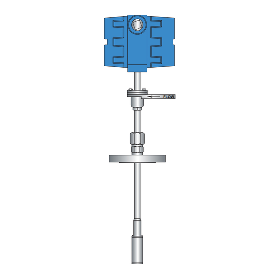
Installation RNG Insertion Meter Installation The RNG series insertion meters are designed to mount on a standard ANSI 150 lb, 2 in . pipe flange . If the main line can be depressurized easily, then a simple installation consisting of a 2 in . nozzle and a 2 in . ANSI 150 Class flange may be used . This permits the shortest shaft length which minimizes the clearance space . -
Page 10: Hot Tap Insertion Flow Meter Installation
Installation Hot Tap Insertion Flow Meter Installation Where de-pressurizing the line for flow meter maintenance is impossible or undesirable, the “hot tap” method of installation is used . This method involves inserting the flow meter through a 2 in . (51 mm) spool piece and a 2 in . (51 mm) full port valve and will require a longer shaft length as well as greater clearance space for removal and installation . -
Page 11: Electrical Installation
Pressure Sensor Input The vortex meter is available in two versions: CE or intrinsically safe for hazardous areas . A display is not available with the intrinsically safe meter . The nameplate specifies the certifications that apply to the meter . Te electrical installation instructions for both types of meters are the same, except the intrinsically safe meter has special consideration specified in this user manual and in the control drawing accompanying the meter . -
Page 12: Instructions Specific To Hazardous Area Installations
INSTRUCTIONS SPECIFIC TO HAZARDOUS AREA INSTALLATIONS See the European ATEX Directive 94/9/EC, ANNEX II, 1 .0 .6 and the Vortex Intrinsically Safe Flow Meters Control Drawing for RWG, RWBG and RNG Meters (shipped with the product; also available at badgermeter.com) . -
Page 13: Operation
HART Communication The vortex meter has the capability of HART Communication . However, it is not required that it be used . In most cases, the meter is configured at the factory per the customer’s specifications . The user need only install the meter and connect power . -
Page 14: Wiring Diagrams
Wiring Diagrams WIRING DIAGRAMS The wiring diagrams illustrated below are for installations where no 4…20 mA pressure sensor is used . Optional wiring diagram for loads > 225 Figure 8: Without 4…20 mA output pressure transducer Page 14 VRX-UM-00374-EN-06 June 2018... - Page 15 Wiring Diagrams If an analog pressure gauge is used, it must be wired as shown below to avoid inadvertent current paths . A single supply can be used to power the flow meter and the external pressure sensor . The 4…20 mA flow indication must be taken from the source side of the loop .
- Page 16 Wiring Diagrams DEVICE SETUP PROCESS VIEW FIELD Process Variable VARIABLES DEVICE Analog Output VARIABLES Percent of Range Vortex Frequency Process Temperature Edit Mode Precess Pressure On / Off Enable / Disable TOTALIZER Total Edit Mode CONTROL Start / Stop Reset...
-
Page 17: Troubleshooting
TROUBLESHOOTING Badger Meter Vortex flow meters are designed to ensure long term accuracy and reliability . The stainless steel body and self- cleaning strut are specifically designed to withstand the rigors of industrial environments . As a result, periodic adjustment or re-calibration is not normally required . - Page 18 Additional Installation Requirements In large pipes, the flow moves slowly at the pipe walls but is at maximum velocity in the center of the pipe creating a continuously variable velocity across the pipe (see Figure 11) . This velocity variation is called the velocity profile of the pipe, and can be measured and plotted by using the insertion flow meter to measure velocities at various noted positions across the pipe .
-
Page 19: Flow Profiling
Additional Installation Requirements Flow Profiling If the flow meter is long enough to be inserted to the far side of the pipe, the flow through the pipe may be profiled at various flow rates . The goal is to find a point in the pipe that remains a consistent percentage of the average flow rate over a wide range of flow . - Page 20 Vortex Flow Meters, RWG/RWBG Wafer Style Flow Meters & RNG Insertion Style Flow Meters Control. Manage. Optimize. Trademarks appearing in this document are the property of their respective entities . Due to continuous research, product improvements and enhancements, Badger Meter reserves the right to change product or system specifications without notice, except to the extent an outstanding contractual obligation exists .
Need help?
Do you have a question about the RWG Series and is the answer not in the manual?
Questions and answers