Table of Contents
Advertisement
Quick Links
Advertisement
Table of Contents

Related Manuals for Vortex MTGB Series


Summary of Contents for Vortex MTGB Series
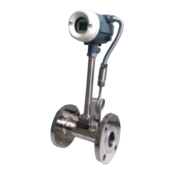
- Page 1 USER MANUAL VORTEX FLOW METER ht t p s : / / p r o m - n a s o s . p r o h t t p s : / / b t s . n e t . u a h t t p s : / / p r o m - n a s o s .
-
Page 2: General Information
7 . Qui c k I nst a l la tion · · · · · · · · · · · · · · · · · · · · · ·· · · · · · · · · · · ·· · · · · · ·· · · · ·· · · · · · ·· · · · ·· · · · · · ·· · · · 19 7. When tightening the Vortex, use а wrench only on the wrench flats. -
Page 3: Technical Data
If any items Wafer: DN15-DNЗ00 Connection are damaged or missing, contact METERN. Measurement Ratio Standard -10: 1 Make sure the Vortex flow model meets your specific needs. For your future reference, it might Ье useful Design to record this information on nameplate in the manual in... - Page 4 Installation conditions Measurable Flow Rate Range: Note: The flow range as blow is for reference only. Consult the factory if you have Installation Take care that flow sensor is always fully filled special requirement. For detailed information see chapter "Cautions Refer to the nameplate or certificate for actual flow range.
- Page 5 3.Flow and density Table two the density of superheated steam with respect to pressure and temperature Table 1 Saturated steam mass flow measurement range Company: kg/ш' Note: when the deпsity valt1e is betweeп two valt1es іп the table, the iпterpolatioп шet\1od сап Ье t1sed to calct1\ate the.
-
Page 6: Mounting Positions
4. Cautions for lnstallation Table three measuring range of liquid and gas 4.1 Mounting Positions Сошраnу: ш'/h • Pip es must Ье fully filled with liquids. lt is essential that pipes remain fully filled at аІІ times, otherwise flow rate indications may Ье affected and measurement errors may Ье... -
Page 7: Speci Al Notice
In addition, cavitation can Ье caused Ьу too little backpressure on the flow meter. For SURE Vortex flow meters, you should provide а backpressure (downstream pressure) of at least 1.25 times the vapor pressure, plus 2 times the pressure drop through the flow meter. -
Page 8: Circuit Description
5. Circuit instructions & Warning: Electrical Hazard Disconnect power before beginning wiring. 5.1 Flowmeter circuit parameters Note: For model with temperature and pressure compensation, the flowmeter Power supply: 12~24VDC/30mA (-20%~+15%); internal power ЗV6 Jithium length should Ье increased50mm compared to the value (А) in table above. battery two automatic switch. -
Page 9: Circuit Connection
MODBUS continuous command minimum interval l00mS; Flow meter working interface includes two interfaces, one is the main interface, one is the auxiliary in terface: 5.3, Circuit connection (1) Main power supply and output signal terminal (middle 4 large hanging frame type terminal) IoutJ GNDJ FoutJ V+ "Iout"... -
Page 10: Modbus Communication
Function desc1•iption Nшnbe1· Set instantaneous flow ш1іt, according to t!ie type of Unit selectio11 flow algorithn1 The default is: mЗ/h Volttme class: mЗ/!1; mЗ/m: 1/h; 1/m Qualityclass: t/h: t/m; kg/!1: kg/m Set flo1v algoritl1m, tl1e instrument according to tl1e algorithm to Algorithm selection Ву... -
Page 11: Troubleshooting
6. Troubleshooting Number of Address offset Operation object Data format data bytes Symptom Probable Санsе Solнtion о Standard flow rate Floating point type Meast1гement is поt Check the parameters (Transmitter, 1. Parameteг wroпg detector factoг and size) асснгаtе Working flow Floating point type 2.
Need help?
Do you have a question about the MTGB Series and is the answer not in the manual?
Questions and answers