Table of Contents
Advertisement
MAKING MODERN LIVING POSSIBLE
Manual
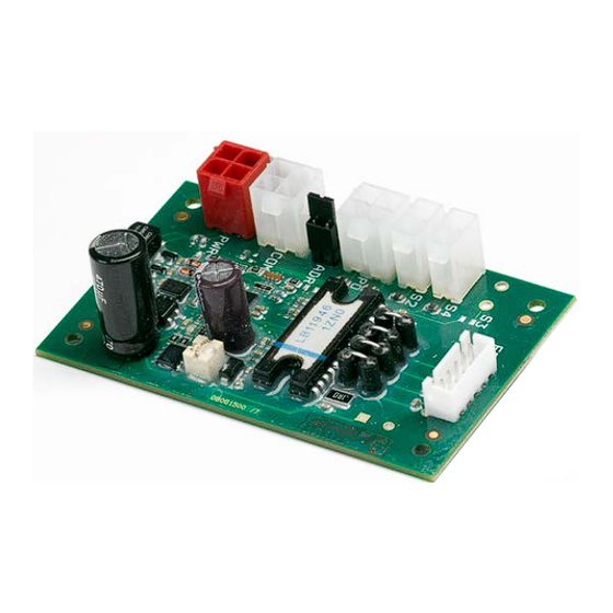
Superheat controller
Type EIM 336
Advantages
Features
DKRCC.PS.RQ0.B7.02 /520H8832
ƒ The evaporator is charged optimally even
when there are large variations in load and
suction pressure.
ƒ The superheat control can save energy
by ensuring optimum utilization of the
evaporator.
ƒ Minimum Stable Superheat search
regulation (MSS).
ƒ Maximum Operating Pressure function (MOP).
ƒ Defrost.
ƒ Compressor protection functions.
ƒ Evaporator temperature (T
de-humidifying.
ƒ Valve driver via Modbus Communication.
ƒ Loss Of Charge indication (LOC).
The EIM 336 is the superheat controller that
can be used to control the opening degree
of a valve based on the superheat of the
evaporator. This is applicable in applications
such as air conditioning, heat pumps and
refrigeration.
An alternative option is to use the controller
in manual mode via modbus communication
and use it as a valve driver by setting the valve
opening degree manually.
ƒ The superheat is controlled to the lowest
stable value.
ƒ It controls EEV in microsteps providing a
smooth superheat curve and less noise.
) control for
e
© Danfoss A/S (AC-MCI / sw), 2014-11
Advertisement
Table of Contents

Related Manuals for Danfoss EIM 336


Summary of Contents for Danfoss EIM 336
-
Page 1: Introduction
MAKING MODERN LIVING POSSIBLE Manual Superheat controller Type EIM 336 The EIM 336 is the superheat controller that can be used to control the opening degree of a valve based on the superheat of the evaporator. This is applicable in applications such as air conditioning, heat pumps and refrigeration. -
Page 2: Table Of Contents
Minimum stable superheat Saturated suction temperature ) Evaporator pressure Evaporator refrigerant outlet temperature Evaporator medium outlet temperature Opening degree Parameter number - is equivalent to the modbus register no. (modbus adress + 1) DKRCC.PS.RQ0.B7.02 /520H8832 © Danfoss A/S (AC-MCI / sw), 2014-11... -
Page 3: Application And Function Overview
Standalone function The EIM 336 is designed to operate in conjunction with a system Manual control master controller, which will control the EIM 336 via modbus. It is... -
Page 4: Technical Specifications
Connector kit for 5x EIM Controller 080G1601 Single pack MYK - EIM interfacer* Single pack 080G0073 * Please contact your local Danfoss supplier for required software Related products Pressure transducer Temperature sensor Programming key / display Electronic Expansion valve AKS 32R, NSK BExx... -
Page 5: Connetions
Power supply for pressure sensor 5 V d.c. Not Used OUT B+ (Orange) OUT A- (Red) Valve OUT B- (Yellow) (EEV) OUT A+ (Black) Common (Grey - Only used for Unipolar) © Danfoss A/S (AC-MCI / sw), 2014-11 DKRCC.PS.RQ0.B7.02 /520H8832... -
Page 6: Configurations
“HWMainSwitch” to 1. This will setup the S4 input to be used as the EIM 336 via modbus. It is however possible to use it as a a hardware main switch. -
Page 7: Modbus Connections
CRC errrors. If the CRC is not correct, the request is is mounted. The secondary unit address “Unit Addr. 2” is used discarded and the EIM 336 waits for a new request. In this case no when the jumper is not mounted. The default primary address is exception response is issued. -
Page 8: Operation
Connecting and setting up a valve When the controller is powered, the valve will first be closed The EIM 336 controller is designed to be used with Danfoss fully so that the controller starts from a known opening degree ETS 6 valves with a maximum of 480 pulses from fully closed to (0%). - Page 9 This requires that the systems main controller continuously this has little practical use. transmits these values to the EIM 336. If no new sensor value is received within 5 seconds of the last transmission, the sensor will revert to using the physical sensors.
- Page 10 Kp proportional gain while in Te control mode --- Kp T e 3116 Tn integration time while in Te control mode ---Tn T e 3117 Te reference while in Te control mode --- T e Reference DKRCC.PS.RQ0.B7.02 /520H8832 © Danfoss A/S (AC-MCI / sw), 2014-11...
- Page 11 “Def Hold Ti 2” seconds. When this time expires the controller resumes normal operation. Note: That defrost is not initiated by the EIM 336, but must be initiated by the master controller. In a standalone configuration the defrost mode is not possible.
-
Page 12: Parameter List
Row text Explanation that they can only be changed when the main switch of the EIM 336 The Parameter Number in the EIM 336 controller. is set to OFF (r12 = 0). This applies for instance to the type of All parameters are addressed as holding register. - Page 13 (power on). Backlash (steps) for spindle play 3035 Backlash compensation. This is active during ü ü normal control 3037 Comp. dir. Compensation direction ü ü 3051 Motor current Motor current ü ü © Danfoss A/S (AC-MCI / sw), 2014-11 DKRCC.PS.RQ0.B7.02 /520H8832...
- Page 14 PNU 50021 at start up. Copy of 2003. This displays the version 64306 SWVer shdw number in a non-EKC format. For example 123 means vers 1.23 DKRCC.PS.RQ0.B5.02 / 520H8256 © Danfoss A/S (AC-MCI / sw), 2014-11...
-
Page 15: Troubleshooting
The force opening of valve function has been implemented in the EIM 336 controller. After startup, this function will provide a constant, set minimum opening degree during a set time period, regardless of the superheat value. The setting parameters are called Start OD% (n17) and StartUp time (n15). -
Page 16: Appendix 1. Interactions
6 : S4 error, (not active) bit 7 : (not active) bit 8 : Close timer bit 8: timer active bit 9 : MOP bit 9 : MOP active. bit 10…15: unused DKRCC.PS.RQ0.B7.02 /520H8832 © Danfoss A/S (AC-MCI / sw), 2014-11... -
Page 17: Appendix 3. Installation - Sensors
Warnings: ƒ Danfoss will not be responsible for any goods, or plant compo- ƒ Accidental damage, poor installation, or site conditions, can nents, damaged as a result of the above defects. It is the give rise to malfunctions of the control system, and ultimately installer’s responsibility to check the installation thoroughly,...
Need help?
Do you have a question about the EIM 336 and is the answer not in the manual?
Questions and answers