Advertisement
Table of Contents
T
E
C
H
N
I
C
A
L
INFO
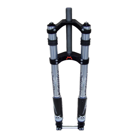
SHIVER DC
2
1
SHIVER SC
GUIDE ASSEMBLY
The guide assembly for the stanchions is installed on the slider top
in all models
the slider by a pilot bushing (1) with an upper bearing support.
Being the pilot bushing very large (92 mm), it offers a wide guiding
surface into the slider for the stanchion tube, so that the fork is very
A
stiff.
The pilot bushing consists of an outer copper support and an inner
B
anti-friction coating. As this coating is very thin, maximum care must
be paid not to damage it when disassembling the slider, otherwise
fork stiffness and performance might decrease.
A
SHIVER
complies with M
SHIVER DC:
2
bushes (A) with a spacer (B) in between.
SHIVER SC:
(C), fitted on the stanchion and a bush (D) fitted on the slider.
Bushes are made of copper and are internally coated with anti-
friction material, which is in contact with the stanchion tube. To
replace them, remove the bushes from slider or stanchion, complete
with plastic spacer, if present.
A washer (2) working as a pilot bushing stopper and seal ring
support is on the pilot bushing.
C
D
2
(SHIVER
models excluded). The tube is guided inside
diagram for cross-country forks.
ARZOCCHI
stanchions are guided into the outer slider by two
stanchions are guided onto the outer slider by a bush
Advertisement
Table of Contents

Related Manuals for Marzocchi SHIVER DC


Summary of Contents for Marzocchi SHIVER DC
- Page 1 (SHIVER models excluded). The tube is guided inside SHIVER DC the slider by a pilot bushing (1) with an upper bearing support. Being the pilot bushing very large (92 mm), it offers a wide guiding surface into the slider for the stanchion tube, so that the fork is very stiff.
-
Page 2: Seal Assembly
ARZOCCHI In the COMMERCIAL type, this push tends to widen the inner lip, MARZOCCHI COMMERCIAL thus worsening ring sealing. The seal ring is kept into its seat by a round circlip (4) with three openings for easy removal from the slider. - Page 3 STANCHIONS Stanchions are made of anodized “EASTON” aluminum or, in some cheaper models, of aluminum alloy. Stanchions are anodized for hardened outer surface and smoother sliding. Stanchion tube thickness may vary according to the fork structure and features. IMPORTANT ! For smooth operation of the stanchions, clean them at regular intervals.
- Page 4 STEER TUBE/CROWN/STANCHION ASSEMBLY “EASTON” aluminium, aluminium steer tube with variable thick- ness or steel steer tube. It is forced onto the yoke and then cut according to the frame size. “BAM” aluminium alloy crown, which is later CNC-machined at the leg and steer tube seats.
- Page 5 ARCH-SLIDER MONOLITH ASSEMBLY This year new feature is the stanchion and arch integrated casting in magnesium alloy. This unit ensures maximum stiffness with limited weight. Apart from its interesting make design, the particular shape of the arch has a wide front side offering large wheel opening, avoiding undesired mud deposit.
- Page 6 Models featuring arch and sliders in two materials and glued together are still being produced. This procedure determines an assembly practically inseparable exploiting also pins (1), retaining Cantilever or V-brake levers, as a joining point between the two parts. IMPORTANT ! Never disconnect the two components! If a disc brake system is installed, it is absolutely forbidden to loosen and remove original pins (1).
-
Page 7: Oil Level
OIL LEVEL The required amount of SAE 7.5 oil is used in all fork models. Apart from possible adjustments through external adjusters, air volume into the fork leg can be modified for fork top performance by increasing/decreasing oil level. In fact, oil amount can affect fork behavior decisively under different working conditions. -
Page 8: Air Pressure
AIR PRESSURE Apart from oil amount in fork legs, in air forks also pressure of air chamber into stanchions can be changed for different fork response Negative air according to rider’s weight and to stresses. New air fork this year is MARATHON model, featuring inner separated air chambers that determine load damping during... -
Page 9: Spring Preload
SPRING PRELOAD For optimal suspension operation and best use of the useful travel, spring preload must be as low as possible. Springs must be able to bear the biker’s weight, being at the lowest possible preload degree. Suspension sagging under the biker’s weight (“sag”) must be about 1/4 of the fork actual travel. -
Page 10: Rebound Adjustment
REBOUND ADJUSTMENT The fork legs section views show the hydraulic configuration determining rebound load damping. The figure shows two spring fork legs: “A” type uses a hydraulic pumping element, anchored to the slider bottom, with limit switch lock spring and adjusting knob that can be reached from fork leg bottom. - Page 11 REBOUND LIMITER (ECC) Rebound limiter causes fork rebound travel stop, thus reducing fork leg height, which is very useful on hard uphill grounds. To enable the rebound limiter, position the knob (1) on left leg top (MARATHON excluded) to “LOCK”. In this way, rebound limit will be determined by current fork leg position;...
- Page 12 HANDLEBAR SUPPORT INFO It is possible to fit on top yoke of SHIVER DC models the support allowing a more advanced handlebar position, with respect to steering tube. This shift can be adjusted in different position thanks to the many...
Need help?
Do you have a question about the SHIVER DC and is the answer not in the manual?
Questions and answers