Advertisement
INSTRUCTIONS
GENERAL RULES
1. Where specified, assemble and disas-
semble the shock absorption system us-
ing the M
shown in the table below.
2. On reassembling the suspension system,
always use new seals.
3. Clean all metal parts with a special,
preferably biodegradable solvent, such
as trichloroethane or trichloroethylene.
4. Before reassembling, lubricate all parts
Z2
in contact with each other using silicone
fat spray.
5. Always grease the conic seal rings be-
Atom
fore reassembling.
6. Use wrenches with metric size only.
Race
Wrenches with inch size might damage
the fastening devices even when their
size is similar to that of the wrenches in
metric size.
special tools only, as
ARZOCCHI
Advertisement
Table of Contents

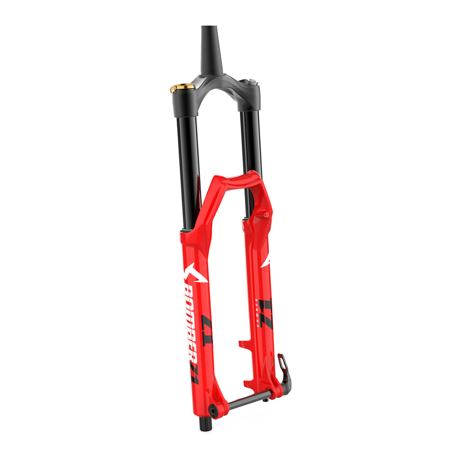
Related Manuals for Marzocchi Z2 Atom Race


Summary of Contents for Marzocchi Z2 Atom Race
- Page 1 INSTRUCTIONS GENERAL RULES 1. Where specified, assemble and disas- semble the shock absorption system us- ing the M special tools only, as ARZOCCHI shown in the table below. 2. On reassembling the suspension system, always use new seals. 3. Clean all metal parts with a special, preferably biodegradable solvent, such as trichloroethane or trichloroethylene.
-
Page 2: Failures, Causes And Remedies
FAILURES, CAUSES AND REMEDIES This paragraph reports some failures that may occur when using the fork. It also indicates possible causes and suggests a remedy. Always refer to this table before doing any repair work. FAILURES CAUSES REMEDIES Oil leaking through the top of slider 1. -
Page 3: Recommendations For Maintenance
RECOMMENDATIONS FOR INSTALLATION MAINTENANCE Installing the fork on a bicycle is a very DISC BRAKE SYSTEM ASSEMBLY delicate operation that should be carried forks are based on advanced WARNING: If a disc brake system ARZOCCHI out with extreme care. The installation should technology, supported by year-long experi- is installed, it is absolutely forbidden always be checked by one of our Technical... -
Page 4: Rebound Adjustment
ADJUSTMENTS SPRING PRELOAD REBOUND ADJUSTMENT REBOUND LIMITER The spring preload determines COMPRES- (only right leg) (only left leg) SION damping and can be adjusted by The right fork leg is equipped with an In case of hard uphill path, fork leg rebound turning the knob (4) on top of the fork legs. -
Page 5: Disassembly Diagram
DISASSEMBLY GENERAL – The reference numbers given in this section relate to the components shown in the forks exploded view. – Before starting any operation, please read the diagram below. It shows the quickest procedure and the exact sequence in which it should be disassembled. - Page 6 SPRING CHANGE FIG. 2 FIG. 3 FIG. 1 (only left leg) Set knob (4) of both legs to minimum Remove preload knob support stop rings Loosen screw (2) and remove rebound preload. (5) from the top of the cap with a small limiting knob (3).
- Page 7 FIG. 4 FIG. 5 FIG. 6 Unscrew the caps (7) with a 21 mm socket Lock the check nuts (39) and remove the Push the stanchions into the sliders. wrench. caps (7) from hydraulic cartridges end Remove the lower washer (10) and the Remove the caps complete with O-ring (8) (12) and (28).
- Page 8 HYDRAULIC CARTRIDGE CHANGE FIG. 8 PILOT BUSHING AND SEAL FIG. 7 Remove hydraulic cartridges (12) and (28) ASSEMBLY CHANGE Drain all oil from the fork legs. and keep the rebound spring. FIG. 9 Pull the crown and stanchions assembly (1) WARNING: Remember to always IMPORTANT: cartridges fitted to forks completely out of the sliders (18).
- Page 9 FIG. 10 FIG. 11 FIG. 12 Use a small screwdriver and remove the Remove the stop ring (14) from the slider Fit the slider protector (A) onto the slider dust seal (13) from the top of the slider. by placing the screwdriver bit in one of the and remove the oil seal (15) with the help three openings on the stop ring and care- of a large slot screwdriver.
- Page 10 FIG. 13 FIG. 14 Remove the upper washer (16) from the Fit the bit of a small screwdriver into the slider. upper edge slot of the pilot bushing (17) and lift gently. Pull the bushing out of the slider and make all necessary changes. Atom Race...
- Page 11 REASSEMBLY CAUTION: before reassembling, clean all FIG. 16 FIG. 17 metal parts carefully with inflammable and Fit the upper washer (16) into the slider so Lubricate the oil seal (15) and place it onto biodegradable solvent and dry them with that it touches the pilot bushing.
- Page 12 FIG. 18 FIG. 19 CROWN AND STANCHIONS Insert the stop ring (14) making sure it is Lubricate the dust seals (13) and fit them ASSEMBLY properly seated into place. into the stanchions from the spring end. FIG. 20 Use buffer (B) to properly seat the ring into Fit the stanchions and crown assembly (1) the slider.
- Page 13 HYDRAULIC CARTRIDGE RE-FITTING FIG. 22 HOW TO FILL WITH OIL FIG. 21 Grease the O-ring (19) on the foot nut (20) FIG. 23 Push the stanchions up to slider bottom. and screw the nut on the threaded end of Pour the oil little by little when the stan- If removed, insert the bottom washers (23, the hydraulic cartridges.
- Page 14 SPRING AND CAP FIG. 25 FIG. 26 FIG. 24 Lubricate the O-ring (27, see exploded Lift the stanchions and start the caps (7) Fit the springs (11) into the stanchions. view) on the top of the preload knob sup- onto the threads by hand. Tighten the caps Slide the preload tube (31) in the LH fork port and the O-ring (8) on the cap (7).
- Page 15 FIG. 27 FIG. 28 FIG. 29 (left leg only) Fit the stop ring (5) of the preload knob Fit the preload knob (4) and secure it on the Set rebound limiting knob (3) on RH leg support and make sure it is properly seated support by tightening the grub screw (6) to adjuster and tighten screw (2) to the torque into place.
Need help?
Do you have a question about the Z2 Atom Race and is the answer not in the manual?
Questions and answers