Table of Contents
Advertisement
Advertisement
Table of Contents

Related Manuals for Unical KON 100


Summary of Contents for Unical KON 100
- Page 1 100 - 115 INSTALLATION AND SERVICING MANUAL...
- Page 2 http://www.unicalag.it/prodotti/professionale-300/light-commercial-alluminio/1626/kon-100 Provisions for proper disposal of the product. At the end of its life cycle the product must not be disposed of as urban waste. It can be taken to a special recycling centre managed by the local authorities, or to a dealer who offers this service. Separate disposal of a domestic appliance avoids possible negative consequences for the environment and human health deriving from inappropriate waste handling and allows the recovery of the materials of which it is made, in order to obtain significant energy and resource savings.
-
Page 3: Table Of Contents
Attention: this manual contains instructions for the exclusive use of the professionally qualified installer and/or maintenance technician in compliance with current legislation. The user is NOT qualified to intervene on the boiler. The manufacturer will not be held liable in case of damage to persons, animals or objects resulting from failure to comply with the instructions contained in the manuals supplied with the boiler. -
Page 4: General Information
Any product repairs must be performed solely by The instruction booklet is an integral and essential personnel authorised by Unical, using original spare part of the product and must be kept by the user. parts only. Failure to comply with the above can... -
Page 5: Symbols Used In The Manual
Any other use must be considered improper. For any damage resulting from improper use, UNICAL AG S.p.A. assumes no responsibility. Use according to the intended purposes also includes strict compliance with the instructions in this manual. 1.4 - INFORMATION FOR THE SYSTEM MANAGER The user must be instructed concerning the use and operation of his heating system, in particular: •... -
Page 6: Safety Warnings
1.5 - SAFETY wARNINGS ATTENTION! The boiler cannot be used by children. The boiler can be used by adults and only after having carefully read the user’s ma- nual. Children should be supervised to ensure that they do not play or tamper with the device. -
Page 7: Technical Data Plate
1.6 - TEchnIcAl dATA PlATE KEY: The cE marking certifies the compliance of the equipment with the essential 1 = CE monitoring body safety requirements defined in the directives and applicable 2 = Type of boiler European regulations and that its functioning satisfy applicable 3 = Boiler model technical standards. -
Page 8: Water Treatment
1.7 - wATER TREATMENT ATTENTION! The treatment of the supply water allows to ANY DAMAGE TO THE BOILER CAUSED BY prevent inconveniences and maintain the THE FORMATION OF FOULING OR BY COR- functionality and efficiency of the generator ROSIVE wATER wILL NOT BE COVERED BY over time. -
Page 9: Technical Features And Dimensions
TECHNICAL FEATURES AND DIMENSIONS 2.1 - TECHNICAL FEATURES 2.2 - DIMENSION FRONT VIEw LEFT SIDE VIEw BACK VIEw VIEw FROM BELOw VIEw FROM ABOVE... - Page 10 2.2 - VIEw wITH THE INDICATION OF THE MAIN COMPONENTS KON 100 LEGENDA Aluminium Heat Exchanger/Capacitor N° C.E. S.E. Description Vent valve Gas valve Condensation drain trap Burner E. RIL. Detection electrode Safety thermostat ACC. Ignition electrode Modulating Pump Water deficiency pressure switch...
-
Page 11: Diagram
Level sensor Flue gas exaust Ø 100 Trunk with suction grille Air intake Ø 80-100 = ERROR CODES see C.E. KON 100 - 115 par. 4.6 Gas inlet G1’’ = WIRING DIAGRAM S.E. KEY see par. 4.5 Heating system G1 1/4’’... - Page 12 5500 6000 6500 7000 Flow rate (l/h) The table provides an indication the flow the pump in function of the Dt of the primary circuit. KON 100 KON 115 Power supply 99,5 Max flow rate demanded (Dt 15 K) 5700...
-
Page 13: General Features
2.5 - OPERATING DATA ACCORDING TO UNI 10348 and GENERAL FEATURES For the adjustment data: NOZZLES - PRESSURE - DIAGRAMS - FLOW RATES - CONSUMPTION refer to the paragraph ADAP- TATION TO OTHER TYPES OF GAS. KON 100 KON 115 Appliance category... - Page 14 2.5.1 - DATA ACCORDING TO ErP DIRECTIVE KON 100 KON 115 Element Symbol Unit Effective nominal output Pnominale Seasonal energy efficiency to heat ƞ the room Season efficiency class to discharge For ch only and combination boilers: useful heat output...
-
Page 15: Installation Instructions
INSTALLATION INSTRUCTIONS 3.1 - GENERAL wARNINGS ATTENTION! ATTENTION! If there is dust and/or if there are his boiler is intended solely for the use for aggressive/corrosive vapours present in which it was expressly designed. Any other the installation room, the appliance must use is to be considered improper and there- be protected suitably and must be able to fore dangerous. -
Page 16: Packaging
Unical AG S.p.A. will not be held liable for damage to persons, animals or objects due to failure to comply with the instruction above. - Page 17 POSITIONING ON THE wALL 3.5 - POSITIONING IN attachment system with bracket. BOILER ROOM Particular importance should be given to local regulations and laws in terms of boiler room and especially the minimum distance that must be kept clear around the boiler. The installation must conform to the requirements contained in the most recent regulations and laws in terms of boiler room, installations of heating and production of hot water, ventilation,...
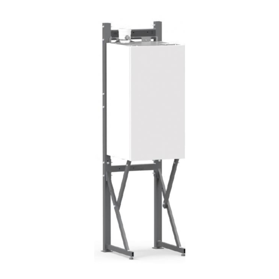
- Page 18 SUPPORT FRAME optional Installation of generators as cascade: For installation instructions, electrical connections, safety devices, refer to MT instruction, available on the website.
-
Page 19: Flue Gas Exhaust Pipe Connection
> 0 = OK - POSSIBLE configuration if < 0 = NO - WRONG configuration (*) Values in the MT018 available on the website. Please note: These values relate to exhausts/ made by means of rigid pipes and smooth original UNICAL. - Page 20 Installation Type c63: Air suction Ø80 and drain Ø100 For this configura- tion use item ‘’ A ‘ (optional). Installation Type B23p: Air suction from top grid and drain Ø100 Air intake is carried out through the grid shown.
-
Page 21: Connections
3.7 - CONNECTION G 1’’ FLOw G 1 1/4’’ RETURN G 1 1/4’’ Danger! The gas connection must be carried out only by Boiler drain cock (to assemble) a qualified installer who must respect and apply that foreseen by relevant laws in force in the local S.cond CONDENSATION DRAIN prescriptions of the supply company. -
Page 22: Filling The System
This could damage the gaskets and cause noise during operation. Unical will not be held liable for damage to persons, animals or objects due to failure to comply with the above instruction. Pressure in the mains supply must be between 0.5 and 6 bar (In case of higher pressure a pres-... -
Page 23: Electrical Connections
3.9 - ELECTRICAL CONNECTIONS Danger! of operation on electrical parts, always disconnect elec- Only a qualified technician may perform the trical power and make sure that it cannot be reconnected electrical installation. accidentally. Before performing connections or any type On/OFF room HSCP Heating Slave Controller Programmer thermostat connection (*) connection (*) - Page 24 Electric power supply connection The boiler is equipped with a power cable, boiler installation requires electric al connection to the mains power supply. This connection must be made up to standard, as required the regulations in force. The power cable must be replaced by technical personnel authorised, using original spare parts only.
-
Page 25: Commissioning
3.10 - COMMISSIONING Commissioning must be done by professionally instruction. qualified personnel. Unical AG S.p.A. will not be Before commissioning the boiler, check that: held liable for damage to persons, animals or objects due to failure to comply with the above... -
Page 26: Measurement Of Combustion Efficiency During Installation
3.11 - MEASUREMENT OF COMBUSTION 3.11.2 - POSITIONING THE PROBES EFFICIENCY DURING INSTALLATION 3.11.1- ACTIVATION OF THE CALIBRATION FUNCTION To determine the combustion efficiency one must make the following measurements: ATTENTION! Function reserved for Authorised Assistance - measurement of the combustion air temperature Centres only. - Page 27 3.12 - ADJUSTING THE BURNER All boilers leave the factory already calibrated and tested, however in the event the gas valve recali- bration are required: The following instructions are intended exclusively for authorised service personnel. 1) Maximum output adjustment - Operate the boiler in “calibration” mode at MAXIMUM OUT- Remove the cap and insert the CO2 analysis probe in the PUT (see 3.11.1) flue gas sample point of the intake/exhaust terminal, see...
- Page 28 NOZZLES - PRESSURE - FLOw RATES TABLE Check the levels of CO2 often, especially with low flow rates. They refer to the boiler with a closed combustion chamber. KON 100 Type of Supply Ø...
-
Page 29: Adaptation Of The Power To The Heating System
3.12.1 - ADAPTATION OF THE POwER TO THE HEATING SYSTEM ATTENTION! Function reserved for Authorised Assistance Centres only. The user is NOT authorised to activate the function described below. It is possible to adjust the maximum thermal capacity in heating Act on parameter FH (par. -
Page 30: Inspection And Maintenance Instructions
4.1 - INSPECTION AND MAINTENANCE INSTRUCTIONS To assure long-term functioning of your appliance and to avoid Once all maintenance operations are complete altering its approved status, only original Unical spare parts resume boiler operation. must be used. • Open the heating flow and return pipes, as well as the cold water inlet valve (if closed previously). - Page 31 1) Measure the Thermal Capacity using a me- It is recommended to use the products ter and compare the value with that contained purposely created by Unical (see sys- tem protection ACCESSORIES sect. in in table 3.12. The data measured indicates if the domestic price list), being careful the exchanger needs cleaning.
- Page 32 4.3 - ADAPTATION TO THE USE OF OTHER GAS The boilers are produced for the type of gas specifically requested Gas Conversion upon ordering. Per la conversione della caldaia da un gas all’altro occorre procedere come segue: DANGER! 1. Remove the front casing The conversion for the operation of the boiler with a type of gas other than that specifically 2.
-
Page 33: Programming Of The Operation Parameters
Continue with the modification of parameters by pressing Press key + (PlUS) / - (MInUS) to modify the (MINUS) Repeat the operations A-B-C to change value VALUE Operazion SET MODIFY PARAMETER FROM DEFAULT KON 100 KON 115 Methane Propane Press the YELLOw key... - Page 34 PUMP OVERRUN - ( 2 ) CAPACITY TO FLOw-RATE RATIO - ( 5 ) Continue with the modification of parameters by pressing Continue with the modification of parameters by pressing the - (MINUS) the - (MINUS) Repeat the operations A-B-C to change value Repeat the operations A-B-C to change value VALUE VALUE...
- Page 35 SETTING OF THE MINIMUM HEATING TEMP. ( 8 ) SETTING OF THE MINIMUM DHw TEMPERATURE (only if combined with an external storage tank) - ( 10 ) Continue with the modification of parameters by pressing Continue with the modification of parameters by pressing the - (MINUS) the - (MINUS) Repeat the operations A-B-C to change value...
- Page 36 ATTENTION! The user is NOT authorised to activate the function de- Function reserved for Authorised Assistance scribed below. Centres only. FA Parameter Symb. Descption Enabled services: 2 = Cascade boiler 3 = Sigle boiler only heating 4 = Sigle boiler + water tank kit Water Δ-temperature protection: 0 = disabled 1÷50 = Massimo Δ-t...
-
Page 37: Wiring Diagram
4.5 - wIRING DIAGRAM 230V 50 Hz APM VM (A) 2.1 1.1 2.2 1.2 E. RIV. + BUS - ROOM STAT E. ACC. KON f SRR SR SRR SR PG DK CPM KON f SL INAIL VM (R) Gas Pressostat Modulating pump Optional KIT Level sensor condensat... -
Page 38: Error Codes
4.6 - ERROR cOdES DIsplay Controller E8 (Optional) For error codes relating to the heating system, refer to the Control panel section “Faults Finding” in Instructions for use supplied with When indicator fault light, the contoller E8. press the LIGHT BLUE key to view the error code on the display. - Page 39 FREEZING Remove power supply, close the gas valve, defrost the EXCHANGER (24) heat exchanger carefully. Is detected, the freezing of the heat exchanger. If the heating sensor detects a temperature below 2 ° C, the burner ignition is inhibited until the sensor detects a temperature higher than 5 °...
-
Page 40: Notes
4.7 - NOTE Check and clean the condensate trap In order to check and clean the siphon carry out the following steps: disconnect the transparent pipe (A) pag. 21 check that no deposits have accumulated inside the siphon. If there are any deposits flush them out with clean water;... - Page 41 gasket between the distributor and heat exchanger Remove the gas flange ‘’ A ‘’ from the mixer fan, DANGER! remove the 8 screws ‘’ B ‘’ burner plate and proce- It is absolutely necessary to replace the ed to clean the burner and heat exchanger body. gasket at any time the inspection or mainte- nance is made on the burner.
- Page 44 - export@unical-ag.com - www.unical.eu Unical declines every responsibility for the possible inaccuracies if owed to errors of transcript or press. Also reserves the right to bring those changes that it will hold necessary to it own products or profits, without jeopardizing its essential characteristics.
Need help?
Do you have a question about the KON 100 and is the answer not in the manual?
Questions and answers