
Subscribe to Our Youtube Channel
Related Manuals for Unical ELLPREX Series


Summary of Contents for Unical ELLPREX Series
- Page 1 ELLPREX INSTALLATION, USE AND SERVICING INSTRUCTION 26739 - 01/13 (to be kept by the user) rev. 4...
- Page 2 Preserve with care the book for every further consultation. This manual supplies a summary of what has to be followed during the installation, use and servicing of the UNICAL boilers, ELLPREX range. In the course of this text the short name ELL can be used to indicate the ELLPREX boiler.
- Page 3 Installation and Servicing Instructions or as otherwise recommended by Unical in writing. If in doubt please inquire. Any direct connection of a control device not approved by Unical could invalidate the certification and the normal appliance warranty. Notes.
-
Page 4: Table Of Contents
CONSTRUCTIONAL-DIMENSIONAL TECHNICAL CHARACTERISTICS ....page Construction of the ELLPREX boilers ........page Working principle ..............page Dimensions and hydraulic connections ........page INSTALLATION ..............page Packaging ................page Handling ................. page Positioning in the boiler house ..........page Connection to the chimney ............. page Water connections .............. -
Page 5: Constructional-Dimensional Technical Characteristics
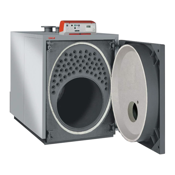
CONSTRUCTIONAL-DIMENSIONAL TECHNICAL CHARACTERISTICS 1.1 - CONSTRUCTION OF THE ELLPREX BOILERS The ELLPREX boilers are of horizontal type (oval till the ELL 970 and cylindrical from ELL 1100) with flame reversion in the combustion chamber and with third pass in the smoke pipes. - Page 6 1.3 - DIMENSIONS AND HYDRAULIC CONNECTIONS FOR ELLPREX 170÷630 fig. 2 Panel board T1 C.H. flow T5 Flue socket Burner fixing plate T2 C.H. return T6 Max. burner blast tube dia. Smoke chamber cleaning door T3 Expansion vessel connection Sight glass T4 Boiler drain ELLPREX Nominal...
- Page 7 DIMENSIONS AND HYDRAULIC CONNECTIONS FOR ELLPREX 760÷970 fig. 5 Panel board T1 C.H. flow T5 Flue socket Burner fixing plate T2 C.H. return T6 Max. burner blast tube dia. Smoke chamber cleaning door T3 Expansion vessel connection Sight glass T4 Boiler drain ELLPREX Nominal Nominal...
- Page 8 DIMENSIONS AND HYDRAULIC CONNECTIONS FOR ELLPREX 1100÷2650 fig. 7 Panel board T1 C.H. flow T5 Flue socket Burner fixing plate T2 C.H. return T6 Max. burner blast tube dia. Smoke chamber cleaning door T3 Expansion vessel connection T7 Sludge drain Sight glass T4 Boiler drain T8 Inspection door...
- Page 9 DIMENSIONS AND HYDRAULIC CONNECTIONS FOR ELLPREX 3000÷4000 fig. 11 Panel board T1 C.H. flow T5 Flue socket Burner fixing plate T2 C.H. return T6 Max. burner blast tube dia. Smoke chamber cleaning door T3 Expansion vessel connection T7 Sludge drain Sight glass T4 Boiler drain T8 Inspection door...
- Page 10 DIMENSIONS AND HYDRAULIC CONNECTIONS FOR ELLPREX 4500÷7000 T2-T3-T1 fig. 14 Panel board T1 C.H. flow T5 Flue socket Burner fixing plate T2 C.H. return T6 Max. burner blast tube dia. Smoke chamber cleaning door T3 Expansion vessel connection T7 Inspection door Sight glass T4 Boiler drain Nominal...
-
Page 11: Installation
INSTALLATION 2.1 - PACKAGING The ELLPREX boilers are supplied complete and R of the ordered boiler, shown in the already fitted. previous tables and that the cartons, containing In addition to the a. m. panel board, packaged with door and smoke chamber already fitted, whilst the casing with the insulation the casing, or part of it, are marked with the in its own carton, in the combustion chamber,... -
Page 12: Connection To The Chimney
2.4 - CONNECTION TO THE an approved boiler putty so that the inlet of fresh In the flue pipe, between the boiler and the CHIMNEY air, with consequent increase of the possibility chimney, convenient sampling points for of condensate formation, is avoided. smoke temperature and combustion products The chimney has a foundamental importance for Furthermore the possible condensate or rain... -
Page 13: Shunt Pump
The expansion pipe connects the C.H. system to NO gate valve on it. the expansion vessel. This pipe which starts from the connecting point T3 (see table DIMENSIONS), must have 2.5.6 - SHUNT PUMP installed between the flow and return The ELLPREX boilers must always operate in Q = P x 22 connections, upstream an eventual 3 or 4 way... -
Page 14: Important Note
2.6.3 - BOILERS “ELL 1100-ELL 6000” For all these models the hinging and the fixing of the door are made according to the schema of fig. 19. In these cases the two hinges on the L.H. side are normally used as rotating hinges (from Right to Left), whilst the two ones on the R.H. -
Page 15: Conformity Of The Burner
2.7 - BURNER the following directives and standards: EN 676 - Automatic forced draught burners 2.7.1 - CONFORMITY OF THE BURNER Gas Appliances Directive (90/396/CEE); for gaseous fuels. EMC Directive (89/336/CEE). All the burners equipping the ELLPREX boilers EN 267 - Automizing oil burners of must be CE certificated and must conform to monobloc type - Testing - 2.7.2 - CHOICE OF THE BURNER... -
Page 16: Connection Of The Sightglass To The Burner Via Acooling Line
2.8 - CONNECTION OF THE SIGHTGLASS TO THE BURNER VIA A COOLING LINE The flame sightglass is equipped with a 1/8" threaded connection (pos. 1) on which a pressure test nipple (9mm dia.) is fitted. This can be used with a silicon pipe for the measurement of the counterpressure in the combustion chamber. - Page 17 ELLPREX 170÷630 fig. 22 Assembly of the casing should be carried out in the following steps: Refer to diagram on fig. 22 for details A. Fit the insulation blanket (1) onto the boiler shell and secure it in to place using the elasticated straps (2) provided, ensuring that the metal clips grip in to the external surface of the insulation.
- Page 18 ELLPREX 760÷970 fig. 24 D) Fit the rear insulation (7), fix the rear lower supplied. Mounting sequence (Ref. fig. 24) panel (9) hook the upper rear panel (10) to Fix the side cable clamp plates (5) to the A) Fit the insulation blanket (1) onto the boiler the screws (8).
- Page 19 ELLPREX 1100÷2200 fig. 25 D) Fit the rear upper panel (7). casing side panels (3a & 4a). Mounting sequence (Ref. fig. 25) Fit the plastic cable clamps (8) to the upper Fit the cables, leaving the boiler from the A) Fit the insulation blanket (1) onto the boiler rear panel (7).
- Page 20 ELLPREX 2650 fig. 26 rear panel (6). cable clamps (7). Mounting sequence (Ref. fig. 26) D) After removal of the two side screws from F) Position the upper panels (9 and 10) and A) Fit the insulation blanket (1) onto the boiler the panel board rotate its cover towards the press them against the side panels.
- Page 21 ELLPREX 3000 - 4000 fig. 27 To determine which one of the front side in the bulb holders as shown in fig. 28 and Mounting sequence (Ref. fig. 27) panels is the left or the right ensure that connect the mains, the burner, the pump(s) A) Fit the insulation blanket (1) onto the boiler the cable clamp plates (5) are positioned and any ancillary equipment to the panel...
- Page 22 Sequence of bulbs introduction Introduce the sensors in the upper bulb holder(s) in the following sequence (Ref. to fig. 28): - thermometer (1) - working thermostat (2) - high limit thermostat (3) - minimum thermostat (4). We recommend that the introduction of the sensors is made up to bottom of the bulb holder(s).
- Page 23 Sequence assembly (see fig. 29) The boilers ELL 4500 to ELL 7000 are supplied with the casing already mounted., therefore for the assemblage of the panel board, to proceed in the following way: A) Get off the two R.H. side upper walkways (pos. 1 and 2). ELLPREX 4500÷7000 B) Attach the box to the instrument panel support bracket on the right side of the boiler.
-
Page 24: Standard Panel Board
STANDARD PANEL BOARD 3.1 - PANEL BOARD TYPE 21057 - FUNCTIONS DESCRIPTION Through the main switch 11 the panel board and all the equipments connected to it will be under power. The switches 12 & 13 switch On and OFF the power to the burner and the Heating pump (via a relay, if necessary). -
Page 25: Introduction Of The Electronic Panel Board Type 30688
The ELLPREX boilers can be supplied with The mixing valve and the relevant motor are an electronic panel board complete with a digital not supplied by Unical. outer compensator with built-in microcomputer When the room sensor is not fitted (it is and permanent memory. - Page 26 3.5 - ELECTRICAL WIRING DIAGRAM FOR SINGLE PHASE BURNER AND PUMPS TERMINAL OF KROMSCHRÖDER OUTER COMPENSATOR F1 (max 4 A) 230V~ 50Hz 230V~ 50Hz (max 4A) (max 4A) (30°C) (100°C) (30°÷90°C) Ipi2 Ipi1 2nd stage Seven pole connector Ph Phase (230V ~ 50Hz) Ipi2 Pump switch for C.H.
-
Page 27: Outer Compensator
3.6 - OUTER COMPENSATOR On how to adjust or to program the outer parameters, which are "not changeable" and compensator, please refer to the instruction the parameters which are adjustable by the manual supplied with the outer compensator. user according to his needs. In the following table we list the factory set PARAMETERS PROGRAMMABLE BY A TECHNICIAN AND PROTECTED BY AN ACCESS CODE INSTALLATION... - Page 28 HEATING CIRCUIT 1 Designation Value range Default HC FUNCTION 00 - 04 PUMP MODE 00 , 03 MIXER OPEN 5 - 25 (not for HW circuit) MIXER CLOSE 5 - 25 (not for HW circuit) MAX FLOW-T 80 °C 20 °C - 110 °C MIN FLOW-T 10 °C - 110 °C 10 °C...
- Page 29 PARAMETERS PROGRAMMABLE BY THE USER PARAMETERS DISPAYED AT THE COMMISSIONING STAGE Start INSTALLATION, Set value, Save value and next value GERMAN Set language TIME Set current time: 1. Minute 2. Hour YEAR Set current date MONTH Set current date Set current date BUS ID 1 1 1 1 1 Enter heating circuit number “1”: 00-15...
- Page 30 HEATING CIRCUIT 1 Designation Value range Default MODE - - - - - - - - T-ROOM DES 1*) 5 °C - 40 °C 20 °C T-ROOM DES 2 5 °C - 40 °C 20 °C T-ROOM DES 3 5 °C - 40 °C 20 °C ECONO TEMP *) 5 °C - 40 °C...
- Page 31 HEAT CIRCUIT 1 Designation Value range HEAT PROGRAM 1 Mo. / Tu. / We. / TH. / Fr. : 06:00 to 22:00 FACTORY SETTING: Sa. /Su. : 07:00 to 23:00 HEAT PROGRAM 2 Mo. / Tu. / We. / TH. / Fr. : 06:00 to 08:00, FACTORY SETTING: 16:00 to 22:00...
-
Page 32: Electrical And Hydraulic Connections Of C.h
3.7 - ELECTRICAL AND HYDRAULIC CONNECTIONS OF C.H. In the fig. 35 the typical connection of the boiler to C.H. system with two heating zones, of which one is with motorized mixing valve. Both, the heating zones are controled by an outer compensator. -
Page 33: Commission And Operation
COMMISSIONING AND OPERATION 4.1 - POSITIONING OF THE TURBULATORS The ELLPREX boilers are designed to be used in an output range to improve the seasonal efficiency and the possibility to be adopted in all the heating installations. The output must be adjusted at the commissioning stage, according to the system designer indications and, in any case, within the operation range for each boiler model... -
Page 34: Preliminary Check
Turbulators removal Detail 1: Detail 2: Detail 3: Fit the brush handle extension Fit the pin in the radial hole with a hammer. Screw the turbulator remover onto the onto the turbulator remover turbulator. Withdraw the pin from turbulator. Detail 4: Detail 5: Detail 6: Turn up to unblock the turbulator. -
Page 35: Operation Of The Boiler
4.4 - OPERATION OF THE BOILER standard equipped with inspection hand holes, The room temperature will be compulsorily and in the case the presence of limestone, adjusted through a mixing valve and, To ascertain that the form and the dimension of sludges or deposits is found, the opportune eventually, an outer compensator. -
Page 36: Extraordinary Maintenance
cleaning doors on the smoke chamber. that cannot be attributed to the constructive getting result, it will be necessary to replace Besides it will be necessary to verify the good geometry and/or to the materials used and/to the sealing gasket. operation of the protection and control the constructive technique and, therefore, they Similarly it will be necessary to act on the front... - Page 37 Notes...
- Page 38 Notes...
- Page 39 Notes...
- Page 40 Unical AG declines any liability for the inaccuriaces that may appear due to errors in trascription or printing. It also reserves the right to introduce those modifications to its products that it considers necesssary or useful, without compromising the essential characteristics of the said products.
Need help?
Do you have a question about the ELLPREX Series and is the answer not in the manual?
Questions and answers