
Related Manuals for Unical KON R 18


Summary of Contents for Unical KON R 18
- Page 1 R 18 - C 18 - R 24 - C 24 R 28 - C 28 - R 35 - C 35 ISTRUZIONI PER L’INSTALLATORE E IL MANUTENTORE INSTALLATION AND SERVICING MANUAL...
- Page 2 http://www.unicalag.it/prodotti/domestico-50/condensazione-gas/774/kon...
-
Page 3: Table Of Contents
Attenzione il presente manuale contiene istruzioni ad uso esclusivo dell’installatore e/o del manutentore professionalmente qualificato, in conformità alle leggi vigenti. L’utente NON è abilitato a intervenire sulla caldaia. Nel caso di danni a persone, animali o cose derivanti dalla mancata osservanza delle istruzioni conte- nute nei manuali forniti a corredo con la caldaia, il costruttore non può... -
Page 4: Informazioni Generali
L’eventuale riparazione dei prodotti dovrà essere riguardanti la sicurezza di installazione, l’uso e la effettuata solamente da personale autorizzato da Unical AG S.p.A., utilizzando esclusivamente ricambi manutenzione. originali. Il mancato rispetto di quanto sopra può compromettere la sicurezza dell’apparecchio e il Conservare con cura il libretto per ogni ulteriore decadimento della garanzia. -
Page 5: Simbologia Utilizzata Nel Manuale
Qualsiasi utilizzo diverso viene considerato improprio. Per qualsiasi danno risultante da un utilizzo improprio UNICAL AG. S.p.A. non si assume alcuna responsabilità. Un utilizzo secondo gli scopi previsti prevede anche che ci si attenga scrupolosamente alle istruzioni del presente manuale. -
Page 6: Avvertenze Per La Sicurezza
1.5 - AvvERtENZE PER LA SICUREZZA AttENZIONE! La caldaia non deve essere usata da persone con ridotte capacità fisiche, mentali e sensoriali, senza esperienza e conoscenza. Queste persone devono essere precedente- mente istruite e sorvegliate durante le operazioni di manovra. I bambini devono essere sorvegliati affinchè... -
Page 7: Targhetta Dati Tecnici
1.6 - TARGHETTA DEI DATI TECNICI LEGENDA: Marcatura CE 1 = Ente di sorveglianza CE La marcatura CE documenta che le caldaie soddi- 2 = Tipo di caldaia sfano: 3 = Modello caldaia - I requisiti essenziali della direttiva relativa agli apparecchi a gas (direttiva 2009/142/CEE) 4 = Numero di stelle (direttiva 92/42/CEE) - I requisiti essenziali della direttiva relativa alla... -
Page 8: Trattamento Dell'acqua
1.7 - TRATTAMENTO DELL’ACQUA Il trattamento delle acque di alimen- AttENZIONE! tazione consente di prevenire gli QUALSIASI DANNO PROvOCAtO inconvenienti e mantenere funzio- ALLA CALDAIA, DOvUtO ALLA nalità ed efficienza del generatore FORMAZIONE DI INCROStAZIONI O nel tempo. DA ACQUE CORROSIvE, NON SARà COPERtO DA GARANZIA. -
Page 9: Caratteristiche Tecnichee Dimensioni
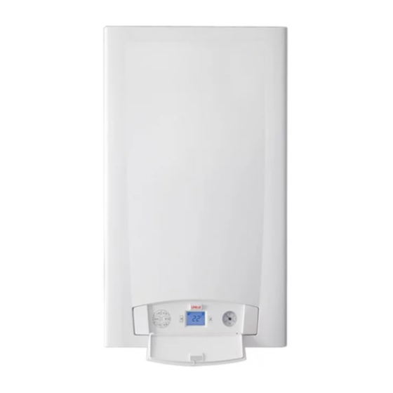
2.1 - CARAttERIStICHE tECNICHE consultare Info tecniche dal sito 2.2 - vIStA CON L’INDICAZIONE DEI COMPONENtI PRINCIPALI E DIMENSIONI KON C 18 - C 24 KON R 18 - R 24 KON C 18 - C 24 vista dall’alto vista da sotto... - Page 10 KON C 28 - C 35 KON R 28 - R 35 KON C 28 - C 35 vista dall’alto vista da sotto...
- Page 11 LEgENDA N° C.E. S.E. Descrizione Valvola di sicurezza Sensore di temperatura acqua By-pass automatico sanitaria SRR Sensore di temperatura ritorno fLS Flussostato con filtro acqua fred- TLC Termostato di sicurezza collettore fumi Valvola gas Scambiatore/Condensatore in Elettrodo di accensione/rileva- alluminio zione Valvola di sfiato /RIL...
-
Page 12: Diagramma Portata / Pressione Disponibile
2.3 - DIAGRAMMA PORTATA/PRESSIONE DISPONIBILE PER L’INStALLAZIONE DIAGRAMMA PORTATA/PRESSIONE DISPONIBILE PER L’INSTALLAZIONE CIRCOLAtORE MODULANtE OPtIONAL DIAGRAMMA PORTATA/PRESSIONE DISPONIBILE PER L’INSTALLAZIONE... -
Page 13: Caratteristiche Generali
2.4 - DAtI DI FUNZIONAMENtO SECONDO UNI 10348 Per i dati di regolazione: UgELLI - PRESSIONI - DIAfRAMMI - PORTATE - CONSUMI fare riferimento al paragrafo ADATTAMENTO ALL’UTILIZZO DI ALTRI gAS. R 18 / C 18 R 24 / C 24 R 28 / C 28 R 35 / C 35 Portata termica massima riscaldamento (ACS) -
Page 14: Istruzioni Per L'installatore
IStRUZIONI PER L’INStALLAZIONE 3.1 - AvvERtENZE GENERALI trollo può essere montato il raccordo tra caldaia e camino/canna fumaria; AttENZIONE! Questa caldaia deve essere desti- AttENZIONE! nata solo all’uso per il quale è stata Se nel locale di installazione espressamente prevista. Ogni altro sono presenti polveri e/o vapori uso è... -
Page 15: Imballo
- Etichetta trasformazione gas ziali fonti di pericolo. La Unical AG S.p.A. declina ogni re- B - Dima in carta predisposizione attacchi sponsabilità nel caso di danni procurati a persone, animali o cose subentranti C - N°... -
Page 16: Posizionamento Della Caldaia
3.5 - POSIZIONAMENtO DELLA CALDAIA Nella scelta del luogo di installazione dell’apparec- Quote di rispetto chio attenersi alle seguenti indicazioni di sicurezza: - Collocare l’apparecchio in locali protetti dal gelo. - Evitare l’installazione in locali con atmosfera cor- rosiva o molto polverosa. - L’apparecchio deve essere installato esclusiva- mente su di una parete verticale e solida che ne sopporti in peso. -
Page 17: Allacciamento Condotto Scarico Fumi
3.6 - ALLACCIAMENtO CONDOttO SCARICO FUMI PER CALDAIE A tIRAGGIO FORZAtO Nel caso di sostituzione di caldaie, sostituire Per l’allacciamento del condotto scarico fumi sono SEMPRE anche il condotto fumi. da rispettare le normative locali e nazionali La caldaia è omologata per le configurazioni di sca- rico sottoriportate: (3%) pendenza verso l’entrata Sistema di canne fumarie collettive compren-... - Page 18 AttENZIONE per questa tipologia di collegamento il lo- cale segue le stesse normative d’installa- zione per le caldaie a tiraggio naturale. Collegamento ad un terminale per il prelievo dell’a- LUNgHEZZA LINEARE ria comburente e scarico fumi mediante camino SDOPPIATO Ø80 individuale o collettivo.
- Page 19 Si consiglia di utilizzare solamente con- consultare la sezione ‘‘Info tecniche’’ dotti di scarico originali Unical. alla pagina della caldaia nel sito E’ esclusa qualsiasi responsabilità www.unicalag.it contrattuale ed extracontrattuale del fornitore per i danni causati da errori nell’installazione e nell’uso e comunque...
-
Page 20: Allacciamenti
3.7 - ALLACCIAMENTO Scarico condensa 3/4’’ La caldaia, durante il processo di combustione, produce condensa che, attraverso il tubo “A”, Pericolo! L’allacciamento del gas deve essere ese- fluisce nel sifone. guito solo a cura di un installatore abilitato La condensa che si forma all’interno della caldaia che dovrà... -
Page 21: Riempimento Dell'impianto
Può danneggiare le guarnizioni e pro- vocare l’insorgere di rumori durante il funzionamento. La Unical declina ogni responsabilità nel caso danni procurati a persone, animali o cose subentranti in seguito a mancata osservanza di quanto sopra esposto. -
Page 22: Allacciamenti Elettrici
La sostituzione del cavo di alimentazio- ne deve essere effettuata da personale tecnico autorizzato UNICAL AG. S.p.A., utilizzando esclusivamente ricambi originali. Il mancato rispetto di quanto sopra può compromettere la sicurezza dell’apparecchio. -
Page 23: Prima Accensione
La Unical AG S.p.A. declina ogni responsabilità nel caso danni pro- Prima della messa in funzione della caldaia è op- curati a persone, animali o cose, suben- portuno verificare quanto segue: l’installazione risponde alle specifiche norme e prescrizioni vigenti sia per quanto riguarda la... -
Page 24: Misura In Opera Del Rendimento Di Combustione
3.11 - MISURA IN OPERA DEL RENDIMENtO DI COMBUStIONE 3.11.1- AttIvAZIONE DELLA FUNZIONE DI tARAtURA AttENZIONE! L’utente NON è autorizzato all’atti- Funzione riservata esclusivamente ai vazione della funzione di seguito Centri di Assistenza Autorizzati. descritta. MINIMA POtENZA AttIvAZIONE girando la manopola (B) in posizione , la cal- Premendo il pulsante (D) per 3 secondi, si attiva daia funzionerà... -
Page 25: Regolazione Del Bruciatore
3.12 - REGOLAZIONE DEL BRUCIAtORE Attenzione, durante queste operazioni Tutte le istruzioni di seguito riportate sono non effettuare prelievi in sanitario. ad uso esclusivo del personale addetto all’assistenza autorizzata. Tutte le caldaie escono di fabbrica già ta- rate e collaudate, nel caso sia necessario eseguire la ritaratura della valvola gas: - Rimuovere il tappo ed inserire la sonda di analisi della CO2 nella presa fumi del terminale aspira-... - Page 26 UGELLI - PRESSIONI - PORtAtE Controllare spesso i livelli di CO2 specialmente alle basse portate. sono riferiti con camera di combustione chiusa. KON R 18 - KON C 18 (*) Diaframma Potenza Tipo di Potenza Portata Press. Velocità Livelli CO...
-
Page 27: Adattamento Della Potenza All'impianto Do Riscaldamento
3.12.1 - ADAttAMENtO DELLA POtENZA ALL’IMPIANtO DI RISCALDAMENtO AttENZIONE! L’utente NON è autorizzato all’attivazione della Funzione riservata esclusivamente ai funzione di seguito descritta. Centri di Assistenza Autorizzati. Agire sul parametro HP (par. 4.2 parametri modi- E’ possibile regolare la portata termica massima in riscaldamento, diminuendo il valore di Potenza ficabili da pannello comandi) per ottenere il valore percentuale del bruciatore. -
Page 28: Istruzioni Per L'ispezionee Manutenzione
• Rimontare il mantello frontale dell’apparecchio. prodotto di serie omologato devono essere utilizzati esclusivamente pezzi di ricambio originali Unical. Qualora si renda necessaria la sostituzione di un componente: • Separare l’apparecchio dalla rete elettrica e accertarsi che non possa essere reinserito acci- dentalmente. - Page 29 Corpo scambiatore di calore ( 9 ) 1) Eseguire misurazione Portata Ter- Si consiglia di utilizzare i prodotti mica tramite contatore e confrontare appositamente creati da Unical il valore ottenuto con quello riportato (vedi listino domestico sez. AC- in tabella 3.12. Il dato rilevato indica CESSORI di protezione impian- se è...
-
Page 30: Parametri Modificabili Da Pannello Comandi
4.2 - PARAMEtRI MODIFICABILI DA PANNELLO COMANDI AttENZIONE! Funzione riservata esclusivamente ai Centri di Assistenza Autorizzati. Alcuni parametri di servizio possono essere modifcati dal pannello comandi: AttIvAZIONE PRERISCALDO VALORI StANDARD Premendo il pulsante (D) per 10 secondi, si attiva la funzione quando la chiave compare sul display in modo lampeggiante SELEZIONE Ruotare la manopola RISCALDAMENTO ‘’B’’... -
Page 31: Adattamento All'utilizzo Di Altri Gas
DISAttIvAZIONE - Accedere alla scheda di modulazione contenuta Per uscire dall’elenco parametri attendere 20” nel quadro elettrico e posizionare il jumper nella o ruotare rapidamente la posizione corrispondente al nuovo tipo di gas manopola sanitaria ‘‘C’’. indicata in figura; 4.3 - ADAttAMENtO ALL’UtILIZZO DI ALtRI GAS Le caldaie sono prodotte per il tipo di gas specifica- tamente richiesto in fase di ordinazione. -
Page 32: Schema Elettrico
4.5 - SCHEMA ELEttRICO Schema di collegamento pratico Kon VIOLA LEGENDA Sensore riscaldamento ritorno A1..A9 Connettori servizi Sonda sanitario (Pred. per modelli R) Controllo pompa modulante Termostato limite Pressostato sicurezza mancanza acqua Termostato limite collettore fumi E. ACC./RIL Elettrodo accensione/rilevazione Valvola gas Flussostato richiesta sanitario Ventilatore modulante Motore valvola deviatrice Morsetti di collegamento Sonda esterna Circolatore... -
Page 33: Codici Di Errore
4.6 - CODICI DI ERRORE ll simbolo lampeggia sul video display quando la caldaia rileva una anomalia. service 1) In caso di anomalia che non provoca il fermo della caldaia, per vi- sualizzare il codice di errore è necessario premere il tasto di sblocco; nel caso la caldaia sia in stand-by il codice di errore compare in modo fisso sul display . - Page 34 vELOCItA’ FUORI Verificare il funzionamento del CONtROLLO ventilatore (18) e le connes- Alterazione della velocità ven- sioni tilatore la velocità non viene raggiunta. vELOCItA’ FUORI Verificare il funzionamento del CONtROLLO ventilatore (18) e le connes- Alterazione della velocità ven- sioni tilatore la velocità...
- Page 35 BLOCCO Verificare l’alimentazione gas Mancanza gas o mancata ac- oppure il buon funzionamento censione bruciatore elettrodo di accensione/rileva- zione (4). FIAMMA PARASSItA Verificare il cablaggio elettrodo fiamma rilevata in accensione Acc/Ril. ed eliminare eventuale ossidazione, premere il tasto di sblocco, se l’anomalia non scompare, sostituire l’elettrodo (4).
- Page 36 http://www.unicalag.it/prodotti/domestico-50/condensazione-gas/774/kon...
- Page 37 Attention: this manual contains instructions for the exclusive use of the professionally qualified installer and/or maintenance technician in compliance with current legislation. The user is NOT qualified to intervene on the boiler. The manufacturer will not be held liable in case of damage to persons, animals or objects resulting from failure to comply with the instructions contained in the manuals supplied with the boiler.
-
Page 38: General Information
Any repairs must be performed solely by personnel authorised by Unical AG S.p.A., using original spare parts only. Failure to comply with the above can Keep the booklet with care for further consultation. -
Page 39: Symbols Used In The Manual
The appliance is designed to work in heating systems, with hot water circulation, for the production of domestic hot water. Any other use is considered improper. For any damage resulting from improper use UNICAL AG. s.p.A. assumes no respon- sibility. Use according to the intended purposes also includes strict compliance with the in- structions in this manual. -
Page 40: Safety Warnings
1.5 - sAFETY wARNINGs ATTENTION! The boiler must not be used by people with with reduced physical, sensory and mental abilities, without experience and knowledge. These people must be previously trained and supervised during the manoeuvre operations. Children must be supervised so that they do not have access to the boiler. -
Page 41: Technical Data Plate
1.6 - TECHNICAL DATA PLATE KEY: CE marking 1 = CE monitoring body The CE marking certifi es that the boilers meet: 2 = Type of boiler - The essential requirements of the gas appliance 3 = Boiler model directive (directive 2009/142/EEC) - The essential requirements of the electromagnetic 4 = Number of stars (directive 92/42 EEC) compatibility directive (2004/108/EEC) -
Page 42: Water Treatment
1.7 - WATER TREATMENT The treatment of the supply water ATTENTION! allows to prevent inconveniences ANY DAMAGE TO THE BOILER and maintain the functionality and CAUsED BY THE FORMATION OF efficiency of the generator over time. FOULING OR BY CORROsIvE wATER wILL NOT BE COvERED BY THE The ideal water pH in heating systems wARRANTY. -
Page 43: Technical Features And Dimensions
Technical Information from the website 2.2 - vIEw wITH THE INDICATION OF THE MAIN COMPONENTs AND DIMENsIONs KON C 18 - C 24 KON R 18 - R 24 KON C 18 - C 24 view from above view from below... - Page 44 KON C 28 - C 35 KON R 28 - R 35 KON C 28 - C 35 view from above view from below...
- Page 45 C.E. S.E. Description Safety valve Domestic hot water temperature Automatic by-pass sensor SRR Return temperature sensor FLS Flow switch with cold water filter TLC Flue gas collector safety ther- Gas valve mostat Ignition/detection electrode Aluminium Heat Exchanger/Ca- pacitor /RIL Vent valve Burner Condensation drain trap Combustion chamber...
- Page 46 2.3 - DIAGRAM OF FLOW RATE/PRESSURE AVAILABLE FOR INsTALLATION DIAGRAM OF FLOW RATE/PRESSURE AVAILABLE FOR INSTALLATION Flow rate (l/h) OPTIONAL MODULATING PUMP DIAGRAM OF FLOW RATE/PRESSURE AVAILABLE FOR INSTALLATION Flow rate (l/h)
-
Page 47: General Features
2.4 - OPERATING DATA ACCORDING TO UNI 10348 For the adjustment data: NOZZLES - PRESSURE - DIAGRAMS - FLOW RATES - CONSUMPTION refer to the par- agraph ADAPTATION TO OTHER TYPES OF GAS. R 18 / C 18 R 24 / C 24 R 28 / C 28 R 35 / C 35 Maximum heating thermal output (DHW) 18.0 (23.4) 23.4 (23.4) 28.0 (28.0) 33.0 (33.0) Minimum heat output (propane) -
Page 48: Installation Instructions
INsTALLATION INsTRUCTIONs 3.1 - GENERAL wARNINGs ATTENTION! If there is dust and/or if there are ATTENTION! aggressive/corrosive vapours This boiler is intended solely for present in the installation room, the use for which it was expressly the appliance must be protected designed. -
Page 49: Packaging
- Certificate of conformity they are potential sources of danger. - Gas conversion label Unical AG s.p.A. will not be held liable for damage to persons, animals or ob- B - Connection predisposition paper template jects due to failure to comply with the instruction above. -
Page 50: Positioning The Boiler
3.5 - POsITIONING THE BOILER When choosing the place of the installation of the Clearance appliance, follow the safety instructions below: - Place the appliance in rooms protected from frost. - Avoid installation in rooms with a corrosive or very dusty atmosphere. -
Page 51: Flue Gas Exhaust Pipe Connection
3.6 - FLUE GAs EXHAUsT PIPE CONNECTION FOR BOILERs wITH FORCED DRAUGHT To connect the flue gas exhaust pipe, local and na- In the event the boiler is replaced, ALwAYs re- tional standards must be observed place the flue gas pipe as well. The boiler is type approved for the exhaust configu- rations listed below: (3%) slope towards inlet... - Page 52 Collective chimney flue system, consisting of two Connection to a terminal for combustion air intake pipes, one for combustion air intake and the other and flue gas exhaust via a single or collective one for combustion products evacuation, coaxial chimney. or double.
- Page 53 "Technical It is recommended to only use original Information" section on the boiler Unical exhaust pipes. page of the www.unicalag.it website The supplier will have no contractual or extra-contractual liability for damage...
-
Page 54: Connections
3.7 - CONNECTION Condensation drain 3/4’’ The boiler, during the combustion process, pro- duces condensation that, through pipe “A”, flows Danger! The gas connection must be carried out into the trap. only by a qualified installer who must re- The condensation that forms inside the boiler flows spect and apply that foreseen by relevant into a suitable drain via pipe “B”. -
Page 55: Filling The System
This could damage the gaskets and cause noise during operation. Unical will not be held liable for dam- age to persons, animals or objects due to failure to comply with the above instruction. -
Page 56: Electrical Connections
3.9 - ELECTRICAL CONNECTIONs Danger! any type of operation on electrical parts, always Only a qualified technician may per- disconnect electrical power and make sure that form the electrical installation. it cannot be reconnected accidentally. Before performing connections or External probe ON/OFF room ON/OFF room connection (*) -
Page 57: Commissioning
3.10 - COMMIssIONING Commissioning must be done by profes- Before commissioning the boiler, check that: sionally qualified personnel. Unical AG S.p.A. will not be held liable for damage to persons, animals or objects due to fail- ure to comply with the above instruction. -
Page 58: Measurement Of Combustion Efficiency During Installation
3.11 - MEAsUREMENT OF COMBUsTION EFFICIENCY DURING INsTALLATION 3.11.1- ACTIvATION OF THE CALIBRATION FUNCTION ATTENTION! The user is NOT authorised to activate Function reserved for Authorised the function described below. Assistance Centres only. MINIMUM OUTPUT ACTIvATION By turning the knob (B) in position , the boiler By pressing the button (D) for 3 seconds, the will operate at minimum output:... - Page 59 3.12 - ADJUsTING THE BURNER Attention, during these operations do not take The following instructions are intended any samples in domestic hot water mode. exclusively for authorised service per- sonnel. All boilers leave the factory already cali- brated and tested, however in the event the gas valve recalibration is required: - Remove the cap and insert the CO2 analysis probe in the flue gas sample point of the intake/...
- Page 60 NOZZLEs - PREssURE - FLOw RATEs TABLE Check the levels of CO2 often, especially with low flow rates. They refer to the boiler with a closed combustion chamber. KON R 18 - KON C 18 (*) Collector Start-up Type of...
-
Page 61: Adaptation Of The Power To The Heating System
3.12.1 - ADAPTATION OF THE POwER TO THE HEATING sYsTEM ATTENTION! The user is NOT authorised to activate the func- Function reserved for Authorised tion described below. Assistance Centres only. Act on parameter HP (par. 4.2 parameters that can It is possible to adjust the maximum thermal capacity in heating mode, by decreasing the burner output be edited from control panel) to achieve the value value. -
Page 62: Inspection And Maintenance Instructions
• Remount the front casing of the appliance. To assure long-term functioning of your appliance and to avoid altering its approved status, only original Unical spare parts must be used. If a component needs to be replaced: • Disconnect the appliance from the electrical mains and make sure that it cannot be reconnected accidentally. - Page 63 It is recommended to use the using a meter and compare the val- products purposely created by ue with that contained in table 3.12. Unical (see system protection The data measured indicates if the ACCESSORIES sect. in the exchanger needs cleaning.
-
Page 64: Parameters That Can Be Edited From The Control Panel
4.2 - PARAMETERs THAT CAN BE EDITED FROM THE CONTROL PANEL ATTENTION! Function reserved for Authorised As- sistance Centres only. Some service parameters can be edited from the control panel: ACTIvATION PREHEATING VALUES FROM DEFAULT By pressing the button (D) for 10 seconds, the function is activated when the key flashes on the display sELECTION... -
Page 65: Adaptation To The Use Of Other Gas
DIsABLING - Access the modulation board contained in the To exit the parameters list wait for 20” or quickly turn electric panel and position the jumper in the the domestic hot water position corresponding to the new type of gas knob ‘‘C’’. -
Page 66: Wiring Diagram
4.5 - wIRING DIAGRAM Practical connection board Kon Return heating sensor A1..A9 Services connectors Domestic hot water probe (Pred. for R models) Modulating pump control Limit thermostat Water deficiency safety pressure switch Flue gas collector limit thermostat E. ACC./RIL Ignition/detection electrode Gas valve Domestic hot water request flow switch Modulating fan Diverter valve motor External probe connection terminals Pump TA1 / OT Modulating TA connection terminals Flow heating sensor On/off TA connection terminals... -
Page 67: Error Codes
4.6 - ERROR CODEs The symbol flashes on the display monitor when the boiler detects an anomaly. service 1) In the event of an anomaly that does not stop boiler operation, press the unblock key to display the error code; in the event the boiler is in stand-by, the error code appears and remains fixed on the display. - Page 68 sPEED OUT OF Check fan operation (18) and CONTROL the connections. Alteration of the fan speed; the speed is not reached. sPEED OUT OF Check fan operation (18) and CONTROL the connections. Alteration of the fan speed; the speed is above that requested. HIGH TEMPERATURE Check pump operation and if Boiler temperature too high.
- Page 69 BLOCK Check the gas supply or that No gas or failed burner ignition. the ignition/detection electrode is working properly (4). PARAsITE FLAME Check the wiring of the Ign/Det. Flame detected upon ignition. electrode and remove any ox- idation, press the unblock key, if the anomaly persists, replace the electrode (4).
- Page 72 - export@unical-ag.com - www.unical.eu Unical declina ogni responsabilità per le possibili inesattezze se dovute ad errori di trascrizione o di stampa. Si riserva altresì il diritto di apportare ai propri prodotti quelle modifiche che riterrà necessarie o utili, senza pregiudicarne le caratteristiche essenziali.
Need help?
Do you have a question about the KON R 18 and is the answer not in the manual?
Questions and answers