Table of Contents
Advertisement
Quick Links
PROPER USE GUIDELINES
Cumulative Trauma Disorders can result from the prolonged use of manually powered hand tools. Hand tools are intended for occasional use and low
volume applications. A wide selection of powered application equipment for extended-use, production operations is available.
The PRO-CRIMPER III Hand Tool is a "Commercial" grade tool and
is designed primarily for field installation, repair, maintenance work,
or prototyping in industrial, commercial, or institutional applications.
Product crimped with this tool will meet the crimp height requirement
for hand tools in the appropriate 114 application specification, but
may not comply with other feature parameters of the specification.
TE Connectivity offers a variety of tools to satisfy your performance
requirements. For additional information, contact the Technical
Assistance Center at 1-800-722-1111.
1. INTRODUCTION
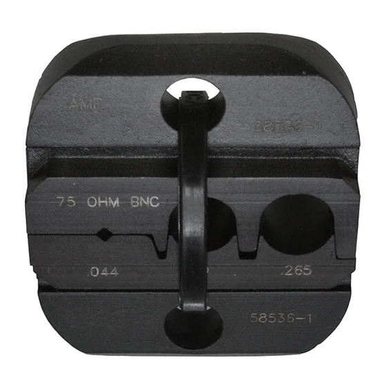
Crimping Die Assembly 58536-1 is designed to crimp 75-Ohm RF Series BNC Dual-Crimp Connectors when
used in PRO-CRIMPER III Frame Assembly 354940-1.
Catalog 82074 provides a guide for cable-to-connector selection. For connectors not referenced in the catalog,
contact TE Product Engineering for recommendations.
Reasons for reissue are provided in Section 8, REVISION SUMMARY.
NOTE
Dimensions in this instruction sheet are in millimeters [with inches in brackets]. Figures and illustrations are for reference only
and are not drawn to scale.
2. DESCRIPTION
The die assembly consists of an indenter die and an anvil die, which when closed form three crimping
chambers. The two larger crimping chambers crimp the ferrule of the connector onto the coaxial cable, and the
smaller crimping chamber crimps the center contact onto the center conductor of the coaxial cable. Each die is
held in the tool jaws by a single screw. See Figure 1.
3. DIE INSTALLATION
(Figure 1)
1. Close the tool handles until the ratchet releases, then allow the tool handles to open fully.
2. Install anvil die in the movable jaw of the tool frame. Align the die with the retaining screw hole, then
secure die with the die-retaining screw. Do NOT fully tighten.
3. Install indenter die in the stationary jaw of the tool frame. Slowly close the tool handles, allowing the
dies to align themselves.
© 2014 TE Connectivity family of companies
All Rights Reserved
*Trademark
TE Connectivity, TE connectivity (logo), and TE (logo) are trademarks. Other logos, product, and/or company names may be trademarks of their respective owners.
Crimping Die
Assembly 58536-1
Indenter Die
Crimping Die
Assembly
58536-1
Anvil Die
Center Contact
Crimping Chamber
Figure 1
TOOLING ASSISTANCE CENTER 1-800-722-1111
PRODUCT INFORMATION 1-800-522-6752
Ferrule
Crimping
Chambers
This controlled document is subject to change.
For latest revision and Regional Customer Service,
visit our website at www.te.com.
Instruction Sheet
408-4028
Rev B
06 JUN 14
PRO-CRIMPER* III
Frame Assembly
354940-1 (Ref)
1 of 4
Advertisement
Table of Contents

Related Manuals for TE Connectivity 58536-1


Summary of Contents for TE Connectivity 58536-1
- Page 1 All Rights Reserved PRODUCT INFORMATION 1-800-522-6752 For latest revision and Regional Customer Service, *Trademark visit our website at www.te.com. TE Connectivity, TE connectivity (logo), and TE (logo) are trademarks. Other logos, product, and/or company names may be trademarks of their respective owners.
- Page 2 408-4028 NOTE Once the anvil has entered the indenter, place a copper bus bar (1.5 ±0.05 [.062 ±.002] diameter) into the center contact crimping chamber of the die assembly. 4. Close the tool handles completely. 5. Securely tighten both screws with the appropriate screwdriver. 4.
- Page 3 408-4028 Crimping the Ferrule Shoulder on Connector Body Butts Against Edge of Die Ferrule in Crimping Chamber on Anvil Die Figure 3 2. Slide the ferrule up over the braided shield and onto the connector until the ferrule butts against the shoulder on the connector body.
- Page 4 (4) the tool has been adjusted correctly. Figure 5 provides information on die opening sizes. 7. REPLACEMENT Crimping Die Assembly 58536-1 is inspected before shipment. TE recommends that the dies be inspected immediately upon arrival at your facility to ensure that the dies have not been damaged during shipment.
- Page 5 Mouser Electronics Authorized Distributor Click to View Pricing, Inventory, Delivery & Lifecycle Information: TE Connectivity 58536-1...
Need help?
Do you have a question about the 58536-1 and is the answer not in the manual?
Questions and answers