Advertisement
PROPER USE GUIDELINES
Cumulative Trauma Disorders can result from the prolonged use of manually powered hand tools. Hand tools are intended for occasional use
and low volume applications. A wide selection of powered application equipment for extended-use, production operations is available.
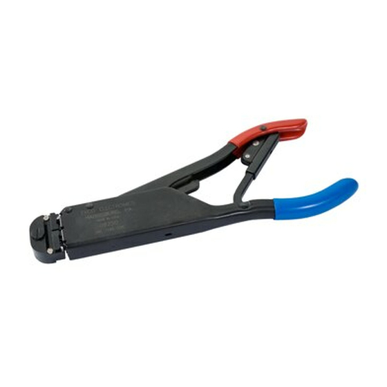
Insulation Adjustment
Locking Screw
Insulation Adjustment
Indicator
Locator
Quick Take-Up
Trigger
Yellow
Handle
CERTI-CRIMP* Hand Crimping Tool Ratchet Control
Figure 1
1. INTRODUCTION
This instruction sheet covers the use of "T"-HEAD
Crimping Tools 59170, 59250, 59275, 59300,
69692-1, and 69693-1. See Figure 1. These tools
crimp:
•
PIDG* vinyl and nylon terminals and splices on
stranded copper wire sizes 26 through 14.
•
STRATO-THERM* terminals on stranded copper
wire sizes 26 through 14.
•
PIDG Insulation Restricting Nylon Terminals on
stranded copper wire sizes 26 through 14.
© 2011 Tyco Electronics Corporation, a TE Connectivity Ltd. Company
All Rights Reserved
*Trademark
TE Connectivity, TE connectivity (logo), and TE (logo) are trademarks. Other logos, product and/or Company names may be trademarks of their respective owners.
"T"-HEAD* Crimping Tools
59170, 59250, 59275, 59300,
69692-1 and 69693-1
Color Code
Reasons for reissue of this sheet are provided in
Information
Section 9, REVISION SUMMARY.
2. DESCRIPTION
The handles of the crimping tools are color-coded to
match the color coding of the product to be applied.
The insulation adjustment indicator is used to control
crimp height of the insulation barrel. It can be set at
any of four positions corresponding to insulation
diameter.
Tools also feature a locator, quick take-up trigger, and
color code information.
The CERTI-CRIMP hand crimping tool ratchet control
ensures full crimping of the product. Once engaged,
the ratchet will not release until the handles have been
FULLY closed.
3. COLOR AND DOT CODING
Note that tool handles and terminal, splice and cap
insulation are color coded for a given wire range as
listed in Figure 2. Crimp the color coded terminal,
splice or cap in the matching color coded portion of the
tool. For example, when using Hand Tool 59275,
yellow coded PIDG terminals and splices and red
coded pre-insulated seated splices must be crimped in
that portion of tool displaying the red and yellow coded
dots and yellow handle. See Figure 1.
TOOLING ASSISTANCE CENTER 1-800-722-1111
PRODUCT INFORMATION 1-800-522-6752
•
PIDG insulation restricting terminals with
TEFLONt coating, used on stranded copper wire
sizes 26 through 14.
•
PIDG Radiation Resistant Terminals and Splices
on stranded copper wire sizes 26 through 14.
•
PLASTI-GRIP* Terminals on solid or stranded
copper wire sizes 22 through 14.
•
PLASTI-GRIP Butt Splices on solid or stranded
copper wire sizes 26 through 22.
•
Spare Wire Caps on solid or stranded copper wire
sizes 22 through 14.
Dimensions on this sheet are in millimeters [with
NOTE
inch equivalent dimensions in brackets]. Figures
and illustrations are for identification only and are
i
not drawn to scale.
The crimping dies bottom before the ratchet
CAUTION
releases. This is a design feature that ensures
maximum electrical and tensile performance of the
!
crimp. Do NOT re-adjust the ratchet.
This controlled document is subject to change.
For latest revision and Regional Customer Service,
visit our website at www.te.com
Instruction Sheet
408-1610
27 APR 11 Rev M
1 of 11
LOC B
Advertisement
Table of Contents

Related Manuals for TE Connectivity 59250


Summary of Contents for TE Connectivity 59250
-
Page 1: Section 9, Revision Summary
PRODUCT INFORMATION 1-800-522-6752 For latest revision and Regional Customer Service, *Trademark visit our website at www.te.com LOC B TE Connectivity, TE connectivity (logo), and TE (logo) are trademarks. Other logos, product and/or Company names may be trademarks of their respective owners. - Page 2 408-1610 Figure 2 (Cont’d) Rev M 2 of 11...
- Page 3 408-1610 Figure 2 (End) Refer to tool label for color code information. Note Crimp the color coded terminals and splices in the NOTE that Figure 2 indicates the number of dots that matching color coded portion of the tool. Refer to appear embossed on a crimped terminal, splice or Section 3.
- Page 4 408-1610 4.2. .Spare Wire Caps 1. Strip wire to dimensions listed in Figure 2. Crimp the color coded portion of the tool. Refer to Section 3. Do not use wire with nicked or missing conductor NOTE strands. 2. Place tool insulation adjustment indicator in Position 4.
-
Page 5: Insulation Crimp Adjustment
408-1610 Figure 6 5. INSULATION CRIMP ADJUSTMENT 2. Place terminal or splice in tool dies. 3. Insert UNSTRIPPED wire into ONLY the 5.1. PIDG Terminals and Splices insulation barrel (see Figure 3 or Figure 4) of PIDG terminals and splices feature a wire NOTE terminal or splice. -
Page 6: Crimp Inspection
408-1610 Figure 7 6. Perform a crimp and repeat adjustment as 2. Set insulation adjustment indicator in Position 3 necessary until desired insulation grip is obtained. for wire having a medium insulation diameter. Do not use a tighter setting than required. 3. -
Page 7: Maintenance And Inspection
408-1610 Use only the crimped items that meet the conditions Flattened shown in the ACCEPT column. Broken Corner REJECT terminals, splices, and spare wire caps can be avoided through careful use of instructions and by performing regular tool maintenance as instructed in this document. -
Page 8: Replacement And Repair
408-1610 Refer to the table in Figure 11 for alternate hard chamber. Carefully try to insert, without forcing, the NOTE gage dimensions for tools 69692-1 and 69693-1. GO element. See Figure 12, Detail A. The GO element must pass completely through the crimping area. - Page 9 408-1610 B. Gaging the Crimping Chamber Using A Solder Slug 4. Measure the compressed solder slug for the wire- and Crimp Height Comparator barrel crimping chamber and check for compliance to dimensions in Figure 9. This inspection requires the use of crimp height comparators, solder slugs, and the dimensions listed 5.
- Page 10 408-1610 Figure 11 Figure 12 7.5. Ratchet Control Inspection 1. Perform a crimp using the largest wire size for your tool. Obtain a .025-mm [.001-in.] shim that is suitable for checking the clearance between the bottoming 2. While holding the wire in place, squeeze the tool surfaces of the crimping dies.
- Page 11 Figure 13 should be replaced by Tyco Electronics to ensure quality and reliability of the tool. Order replacement parts through your TE TOOL NUMBERS AND REPLACEMENT PART NUMBER 591 SHORT HANDLE 59275 SHORT HANDLE 69692-1 69693-1 QTY PER ITEM...
Need help?
Do you have a question about the 59250 and is the answer not in the manual?
Questions and answers