Burkert 8045 Operating Instructions Manual
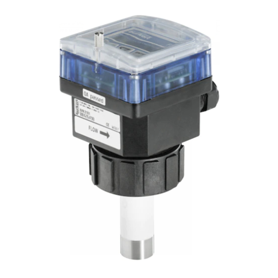
Insertion electromagnetic flowmeter
Hide thumbs
Also See for 8045:
- Instruction manual (144 pages) ,
- Quick start manual (98 pages) ,
- Operating instructions manual (74 pages)

Related Manuals for Burkert 8045


Summary of Contents for Burkert 8045
- Page 1 Type 8045 Insertion electromagnetic flowmeter Magnetisch-induktives Durchfluss-Messgerät, Insertion Débitmètre électromagnétique à insertion Operating Instructions Bedienungsanleitung Manuel d‘utilisation...
- Page 2 We reserve the right to make technical changes without notice. Technische Änderungen vorbehalten. Sous réserve de modification technique. © Bürkert SAS, 2012 - 2019 Operating Instructions 1904/04_EU-ML 00559778 / Original FR...
-
Page 3: Table Of Contents
7.2 7.2.1 Recommandations for installing the 8045 on the pipe .............18 7.2.2 Installation into the pipe of a 8045 with a G2'' nut ..............20 7.2.3 Installation into the pipe of a 8045 with a clamp connection ..........21 7.3 Wiring ......................................21 7.3.1... - Page 4 Type 8045 7.3.4 Wiring the AO1 current output .......................25 7.3.5 Wiring the DO1 transistor output ....................26 7.3.6 Wiring the DI1 digital input ......................26 7.3.7 Wiring the DO2 and DO3 relay outputs ..................27 operAting AnD functions ..............................28 8.1 safety instructions ................................28 8.2 operating levels of the device .............................28 8.3 Description of the navigation keys and the status leDs ................30...
- Page 5 9.1 safety instructions ................................62 9.2 cleaning the device ................................62 9.3 cleaning the flow sensor ..............................63 9.4 replacing the seal on a 8045 with g2" nut ......................63 9.5 if you encounter problems ............................64 9.5.1 Resolution of problems when the device status LED is OFF ..........64 9.5.2 Resolution of problems without message generation but device status LED ON ....64 9.5.3 Resolution of problems without message generation and device status LED green ..66...
-
Page 6: About These Operating Instructions
▶ Indicates an instruction to be carried out to avoid a danger, a warning or a possible risk. → Indicates a procedure to be carried out. 1.2 Definition of the word "device" The word "device" used within these Operating Instructions refers to the insertion electromagnetic flowmeter type 8045. English... -
Page 7: Intended Use
The insertion electromagnetic flowmeter type 8045 is intended exclusively to measure flow rate in liquids. ▶ This device must be used in compliance with the characteristics and commissioning and use conditions specified in the contractual documents and in these Operating Instructions. - Page 8 Type 8045 Intendeduse various dangerous situations To avoid injury take care: ▶ not to use the device in explosive atmospheres. ▶ not to use the device in an environment incompatible with the materials it is made of. ▶ not to use fluid that is incompatible with the materials the device is made of.
-
Page 9: General Information
The condition governing the legal warranty is the conforming use of the device in observance of the operating conditions specified in these Operating Instructions. 4.3 information on the internet You can find the user manuals and technical data sheets regarding the type 8045 at: www.burkert.com English... -
Page 10: Description
5.1 Area of application The insertion electromagnetic flowmeter type 8045 is intended exclusively to measure flow rates in liquids. The device makes it possible to switch a solenoid valve or activate an alarm thanks to a transistor output and, for some versions, by means of two relay outputs, fully configurable and to establish a control loop thanks to a 4...20 mA current output. -
Page 11: Technical Data
Type 8045 Technicaldata TechnicAl DATA 6.1 conditions of use Ambient temperature –10...+60 °C Air humidity < 85 %, non condensated height above see level max. 2000 m operating conditions Continuous equipment mobility Fixed Indoor and outdoor (Protect the device against electromagnetic interference, ultraviolet rays and, when installed outdoors, against the effects of climatic conditions) -
Page 12: Mechanical Data
Screws Stainless steel Flow sensor (exposed to the fluid) PVDF Stainless steel 316L (DIN 1.4404) Seal 8045 with a G2" nut: FKM Earth ring of the flow sensor Stainless steel 316L (DIN 1.4404) or Alloy C22 Electrodes holder PEEK Electrodes Stainless steel 316L (DIN 1.4404) or Alloy C22... -
Page 13: Fluid Data
S020 fitting used is made of. See Fig. 2. • 8045 with flow sensor in PVDF • 0...+80 °C • 8045 with flow sensor in stainless steel • –15...+110 °C fluid pressure The fluid pressure may be restricted by the fluid... - Page 14 Type 8045 Technicaldata transistor output Do1 • type • NPN / PNP (wiring dependent), open collector • function • pulse output (by default), user configurable • frequency • 0...250 Hz • Electrical data • 5...36 V DC, 100 mA max. • 0.5 • duty cycle if f > 2 Hz •...
-
Page 15: Electrical Connection
Type 8045 Technicaldata 6.6 electrical connection type of connection through two m20x1,5 cable glands Cable specifications • cable type • shielded • Cross section • 0.5...1.5 mm • Diameter of each cable: - if only one cable is used per cable gland - 6...12 mm - if two cables are used per cable gland... -
Page 16: Installation And Commissioning
Type 8045 Installationandcommissioning insTAllATion AnD commissioning 7.1 safety instructions Danger risk of injury due to high pressure in the installation. ▶ Stop the circulation of fluid, cut off the pressure and drain the pipe before loosening the process connections. Danger due to electrical voltage. ▶ If a 18...36 V DC powered version is installed either in a wet environment or outdoors, all the electrical volt- ages must be of max. -
Page 17: Fluid Installation Onto The Pipe
▶ Stop the circulation of fluid, cut off the pressure and drain the pipe before loosening the process connections. risk of injury due to the nature of the fluid. ▶ Respect the prevailing regulations on accident prevention and safety relating to the use of aggressive fluids. The insertion electromagnetic flowmeter type 8045 has to be inserted into an S020 fitting mounted on a pipe. English... -
Page 18: Recommandations For Installing The 8045 On The Pipe
Type 8045 Installationandcommissioning 7.2.1 recommandations for installing the 8045 on the pipe → Choose an S020 fitting appropriate to the velocity of the fluid inside the pipe: refer to the graphs below: Example: Flow rate US gpm l/min 100000 • Specification: if the nominal flow rate is 5000... - Page 19 Type 8045 Installationandcommissioning flow direction 50 x DN 5 x DN 40 x DN 5 x DN With control valve Pipe with 2 elbows at 90° in 3 dimensions 25 x DN 5 x DN 20 x DN 5 x DN Pipe with 2 elbows at 90°...
-
Page 20: Installation Into The Pipe Of A 8045 With A G2'' Nut
→ Position the device 1 in order the arrow on the side of the housing indicates the direction of the flow. The totalizers will increment. → Insert the device 1 into the fitting 4. → Tighten the nut 3 by hand on the device 1. Fig. 7 : Installation into the pipe of a 8045 with a G2'' nut English... -
Page 21: Installation Into The Pipe Of A 8045 With A Clamp Connection
→ Tighten by hand the clamp collar 2. → Charge the pipe to make sure the installation is tight. flow direction Fig. 8 : Installation into the pipe of a 8045 with a clamp connection 7.3 Wiring Danger risk of injury due to electrical voltage. ▶ If a 18...36 V DC powered version is installed either in a wet environment or outdoors, all the electrical volt- ages must be of max. -
Page 22: Equipotentiality Of The Installation
Type 8045 Installationandcommissioning notiCe the device is not tight if at least one cable gland is not used ▶ Seal the unused cable gland with the supplied stopper gasket: → Loosen the nut of the unused cable gland. → Remove the transparent disk. → Insert the supplied stopper gasket. → Screw the nut of the cable gland. - Page 23 Type 8045 Installationandcommissioning → Connect the negative power supply terminal to the earth to suppress the effects of common mode currents. If this connection cannot be made directly, a 100 nF / 50 V capacitor can be fitted between the negative power supply terminal and the earth.
-
Page 24: Mounting The Cable Clamp
Type 8045 Installationandcommissioning 7.3.2 mounting the cable clamp → Before wiring the device, insert the supplied cable clamp into the notches of the electronic board. Fig. 11 : M ountign the cable clamp 7.3.3 Terminal assignment and use of the selectors terminal block 1 Iout: 4...20 mA output (AO1) L+: V+ (positive voltage) L–: 0V (power supply ground) PE: functional earth, wired in the factory (see Fig. -
Page 25: Wiring The Ao1 Current Output
Type 8045 Installationandcommissioning ENTER Use the switch B to lock/unlock the key to prevent unauthorized access to the configuration of the device. OFF ON OFF ON ENTER ENTER key is unlocked (default position). key is locked. Fig. 14 : Using the ENTER key lock/unlock switch 1 2 3 4 5 6 Earth cable coming from the housing. -
Page 26: Wiring The Do1 Transistor Output
Type 8045 Installationandcommissioning 7.3.5 Wiring the Do1 transistor output 18-36 V DC 18-36 V DC 300 mA 300 mA 5-36 VDC 5-36 VDC Power supply Power supply Iout L+ L - PE P+ P- Iout L+ L - PE P+ P- Supply PULSE Supply PULSE 18...36 Vdc... -
Page 27: Wiring The Do2 And Do3 Relay Outputs
Type 8045 Installationandcommissioning 7.3.7 Wiring the Do2 and Do3 relay outputs Danger Danger due to the operation of the relay outputs of a ul device in a wet location. ▶ If a UL device is used in a wet location: - energize the relay outputs with an alternating voltage of max. 16 Vrms and 22.6 Vpeak. - or energize the relay outputs with a direct voltage of max. 35 V DC. -
Page 28: Operating And Functions
Type 8045 Operatingandfunctions operATing AnD funcTions 8.1 safety instructions Warning risk of injury due to non-conforming operating. Non-conforming operating could lead to injuries and damage the device and its surroundings. ▶ The operators in charge of operating must have read and understood the contents of this manual. ▶ In particular, observe the safety recommendations and intended use. - Page 29 Type 8045 Operatingandfunctions function Default value function Default value OUTPUT DO2 Hysteresis CUT-OFF 0.000 2–= 0.000 BACKLIT level 9, activated for 30 s 2+= 0.000 K-SENSOR Kw= 1.000 Not inverted FLOW-W. W–= 0.000 W+= 0.000 time delay = 0 Configuration level Process level 12.6 L/s...
-
Page 30: Description Of The Navigation Keys And The Status Leds
Type 8045 Operatingandfunctions 8.3 Description of the navigation keys and the status leDs • Selecting the displayed • Scrolling up the parameter parameters • Confirming the settings • increment the figure selected Status LED of relay DO3 (LED ON = contact closed) Device status LED: see Status LED of relay DO2 (LED ON following table. -
Page 31: Using The Navigation Keys
Type 8045 Operatingandfunctions 8.4 using the navigation keys you want to... press... move between parameters within a level or • to go the next parameter a menu. • to go to the previous parameter 0..9 access the Parameters menu ENTER simultaneously for 5 s, in the Process level... -
Page 32: Details Of The Parameters Menu
Type 8045 Operatingandfunctions 8.6 Details of the parameters menu ENTER To access the Parameters menu, simultaneously press keys for at least 5 s. This menu comprises the following configurable parameters: Choosing the display language LANGUAGE Choosing the flow rate unit, the number of decimals and the unit the totalizers are UNit displayed in. -
Page 33: Choosing The Display Language
Type 8045 Operatingandfunctions 8.6.1 choosing the display language When the device is energized for the first time, the display language is English. LANGUAGE ENGLish DEUtsCh → Confirm the displayed language: The 0..9 FRANçAis selected language is immediately active. itALiANO EsPANOL UNit Fig. 23 : Diagram of the "LANGUAGE" parameter of the Parameters menu → If you do not want to adjust another parameter, go to the "END" parameter of the Parameters menu and press ENTER to save the settings or not and go back to the Process level. - Page 34 Type 8045 Operatingandfunctions → Choose the flow rate unit. UNit FLOw Lit/sEC → Confirm Lit/miN Lit/h m3/miN m3/h → Choose the number of decimal AUtO Us GAL/s 0..9 positions DEC Pt 3 Us GAL/m → Confirm DEC Pt 2 Us GAL/h 0..9...
-
Page 35: Entering The K-Factor Of The Fitting Used
Type 8045 Operatingandfunctions 8.6.3 entering the K-factor of the fitting used The device determines the flow rate in the pipe using the fitting K-factor. The K-factor of the fitting used can be entered here. The device may also determine the K-factor using a Teach-In procedure: see chap. 8.6.4. - Page 36 Type 8045 Operatingandfunctions Determine the fitting k-factor using a teach-in procedure depending on a volume ("teAch v.") The device will use the new K-factor as soon as "SAVE YES" is confirmed when leaving the Parameters menu. → Prepare a tank with a known volume. → Stop the fluid circulation. → confirm "TEACH V.": "FILL END." is displayed.
- Page 37 Type 8045 Operatingandfunctions Determine the fitting k-factor using a teach-in procedure depending on a volume ("teAch f.") The device will use the new K-factor as soon as "SAVE YES" is confirmed when leaving the Parameters menu. → Charge the pipe. → Wait for the flow rate to be stable. → confirm "TEACH F.": "MEASURE \" is displayed.
-
Page 38: Configuring The Outputs (General Diagram)
Type 8045 Operatingandfunctions 8.6.5 configuring the outputs (general diagram) Parameterizing the 4...20 mA analogue output, AO1. See chap. 8.6.6. OUtPUt Configuring the transistor output DO1 as a pulse PULsE output. See Fig. 30, chap. 8.6.7. Configuring the transistor output DO1 to switch a load hYstEREs. -
Page 39: Configuring The Ao1 Current Output
Type 8045 Operatingandfunctions 8.6.6 configuring the Ao1 current output The current output gives a 22 mA current when the device shows an operation fault, even if the current output is disabled. The 4...20 mA output provides an electrical current, the value of which reflects the flow rate measured by the device. -
Page 40: Configuring The Transistor Output Do1 As A Pulse Output
Type 8045 Operatingandfunctions 8.6.7 configuring the transistor output Do1 as a pulse output When the DO1 transistor output is configured as a pulse output, a pulse is transmitted on the output each time the parametered volume of fluid has been measured by the device. Is only displayed if the unit chosen in the "UNIT"... -
Page 41: Configuring The Transistor Output Do1 To Switch A Load Depending On Two Threshold Values
Type 8045 Operatingandfunctions 8.6.8 configuring the transistor output Do1 to switch a load depending on two threshold values OUtPUt hYstEREs. 1-= 0.000 wiNDOw → Enter a flow rate value , associated to the low threshold, in the unit chosen in the "UNIT" parameter. → Confirm. 1+= 0.000 → Enter a flow rate value , associated to the high threshold, in the unit chosen in the "UNIT"... - Page 42 Type 8045 Operatingandfunctions hysteresis switching The output status changes when a threshold is reached: • by increasing flow rate, the output status changes when the high threshold X+ is reached. • by decreasing flow rate, the output status changes when the low threshold X– is reached.
-
Page 43: Configuring The Transistor Output Do1 To Switch A Load When The Fluid Direction Changes
Type 8045 Operatingandfunctions 8.6.9 configuring the transistor output Do1 to switch a load when the fluid direction changes The DO1 transistor output can be configured to indicate the fluid circulation change. When the measured flow rate is in the cut-off flow range (see chap. 8.6.16), the flow rate is set to 0 and positive. -
Page 44: Configuring The Transistor Output Do1 To Switch A Load When A Warning Message Is Emitted By The Device
Type 8045 Operatingandfunctions 8.6.10 configuring the transistor output Do1 to switch a load when a warning message is emitted by the device When the device generates a warning message, the device status LED is orange. The generation of a warning message can also be indicated by the switching of the transistor output. OUtPUt wARNiNG iNV YEs 0..9 iNV NO →... - Page 45 Type 8045 Operatingandfunctions OUtPUt hYstEREs. 2–= 0.000 wiNDOw → Enter a flow rate value , associated to the low threshold, in the unit chosen in the "UNIT" parameter. → Confirm. 2+= 0.000 → Enter a flow rate value , associated to the high threshold, in the unit chosen in the "UNIT"...
- Page 46 Type 8045 Operatingandfunctions When the measured flow rate is in the cut-off flow range (see chap. 8.6.16), the flow rate is set to 0 and positive. The following diagram shows the behaviour of the DO output when it is configured to indicate the fluid circulation changes, when the CUT-OFF function is used.
-
Page 47: 8.6.12 Configuring The Di1 Digital Input
Type 8045 Operatingandfunctions When the device generates a warning message, the device status LED is orange. The generation of a warning message can also be indicated by the switching of the relay output. OUtPUt wARNiNG iNV YEs 0..9 iNV NO → Choose the operating, inverted or not inverted, of the relay output. - Page 48 Type 8045 Operatingandfunctions Calibration of the flow zero point is described in chap. 8.7.2. iNPUt CALiB 0 iNV YEs 0..9 iNV NO → Choose "INV. NO" to trigger the calibration of the zero flow point on the leading edge. → Choose "INV. YES" to trigger the calibration of the zero flow point on the trailing edge.
- Page 49 Type 8045 Operatingandfunctions The preset flow rate is ignored if there is a running check for the correct behaviour of the outputs (see chap. 8.7.3). This function makes it possible, like the Hold mode, to freeze the flow rate measure, but to a preset value set by the user.
- Page 50 Type 8045 Operatingandfunctions The Hold Tot. mode is used to freeze the totalizers while carrying out maintenance work. In practice, when the device is in Hold Tot. mode: • the totalizers do not increment any more. • the device status LED flashes.
-
Page 51: 8.6.13 Configuring The Filter Of The Measured Flow Rate
Type 8045 Operatingandfunctions 8.6.13 configuring the filter of the measured flow rate This parameter makes it possible to dampen the fluctuations: • of the display, • of the AO1 current output. Ten filters are available. When the "fast" filter is active and the flow rate varies for ±30 % (for example when charging the pipe or stopping the flow), the filter is disabled: the new flow rate is immediately taken into account by the device. -
Page 52: 8.6.14 Resetting Both Totalizers
Type 8045 Operatingandfunctions 8.6.14 resetting both totalizers This parameter makes it possible to reset both totalizers. Both totalizers are reset upon confirmation of "SAVE YES" when leaving the Parameters menu. tOtAL REsEt N 0..9 REsEt Y → Choose to reset both totalizers or not. -
Page 53: 8.6.16 Parameterizing The Cut-Off Flow Rate
Type 8045 Operatingandfunctions 8.6.16 parameterizing the cut-off flow rate This parameter makes it possible to set the flow rate value to 0 if the measured value is less than the set cut-off value: • the display then shows a flow rate = 0 (a dot is displayed after the flow rate units). -
Page 54: Setting The Brightness Of The Display And How Long It Stays On, Or Deactivating The Backlight
Type 8045 Operatingandfunctions 8.6.17 setting the brightness of the display and how long it stays on, or deactivating the backlight This parameter makes it possible: • to adjust the brightness of the display and how long the display is backlit after a key press. • to deactivate the backlight. BACKLit BKLG= 1 → Set the display brightness, from 1 to 9. -
Page 55: Details Of The Test Menu
Type 8045 Operatingandfunctions 8.7 Details of the Test menu ENTER To access the Test menu, simultaneously press keys for at least 5 s. 0..9 This menu comprises the following configurable parameters: Adjusting the 4...20 mA output CAL AO1 Calibrate the flow zero point of the device. -
Page 56: Adjusting The Current Output
Type 8045 Operatingandfunctions 8.7.1 Adjusting the current output This parameter makes it possible to adjust the value of the current transmitted on the analogue output. CAL AO1 OFFsEt OF= 4.05 → The device generates a 4 mA current. → Measure the current given on the 4...20 mA output using a multimeter. -
Page 57: Calibrating The Flow Zero Point
Type 8045 Operatingandfunctions 8.7.2 calibrating the flow zero point Adjust this parameter: • before carrying out a Teach-In procedure of the K-factor. • after maintenance work. • if the measured flow rate is not zero whereas the fluid circulation has been stopped. Make sure there are no bubbles in the pipe. -
Page 58: Checking The Outputs Behaviour
Type 8045 Operatingandfunctions → Charge the pipe. → Stop the fluid circulation. → Make sure the fluid is still. CALiB. 0 CALiB N 0..9 CALiB Y → Choose "CALIB Y". mEAsURE / The device calibrates the flow zero point. The calibration has... -
Page 59: Setting The Kw Coefficient Of The Flow Sensor
Type 8045 Operatingandfunctions FLOw sim=12,50 → Enter a flow rate value. ENTER → Confirm by pressing the key. → Check that the outputs are behaving as expected. ENTER → To test another value, press → To exit the checking, press 0..9 Fig. 55 : Diagram of the "FLOW" parameter of the Test menu ... - Page 60 Type 8045 Operatingandfunctions • To disable the flow rate monitoring, set W– = W+ = 0. • To disable one of the limits, set it to 0. FLOw-w. w-= 0.000 → Enter a flow rate value (in the unit chosen in the "UNIT" parameter), below which a "WARN LO"...
-
Page 61: Details Of The Information Menu
Type 8045 Operatingandfunctions 8.8 Details of the information menu • This menu is available when the device status LED is orange or red. • For the meaning of a message, go to chap. 9.5.4 and 9.5.5. To access the Information menu, press the key for at least 2 s, in the Process level. -
Page 62: Maintenance And Troubleshooting
Type 8045 Maintenanceandtroubleshooting mAinTenAnce AnD TroubleshooTing 9.1 safety instructions Danger risk of injury due to high pressure in the installation. ▶ Stop the circulation of fluid, cut off the pressure and drain the pipe before loosening the process connections. Danger due to electrical voltage. ▶ Disconnect the electrical power for all the conductors and isolate it before carrying out work on the system. -
Page 63: Cleaning The Flow Sensor
Type 8045 Maintenanceandtroubleshooting 9.3 cleaning the flow sensor notiCe ▶ Use a cleaning product that is compatible with the materials the flow sensor is made of. ▶ Do not use any abrasive acting materials. notiCe After cleaning of the flow sensor: ▶ Rince the flow sensor. -
Page 64: If You Encounter Problems
Type 8045 Maintenanceandtroubleshooting 9.5 if you encounter problems 9.5.1 resolution of problems when the device status leD is off Device current output Do1 message possible cause recommended action status output and/or Do2 displayed and/or Do3 → Check that the supply 0 mA low level "PWRFAIL" The supply voltage is too low. voltage is between 18 and 36 V DC. - Page 65 Type 8045 Maintenanceandtroubleshooting Device current output Do1 problem recommended action status leD output and/or Do2 and/or Do3 → Check the configuration of the current any colour 4 mA depending on The current output the thresholds transmits 4 mA output. See chap. 8.6.6. or switched whatever the displayed flow rate value.
-
Page 66: Resolution Of Problems Without Message Generation And Device Status Led Green
Type 8045 Maintenanceandtroubleshooting 9.5.3 resolution of problems without message generation and device status leD green Device current output Do1 possible cause recommended action status output and/or Do2 and/or Do3 → Check that the K-factor corresponds green 4...20 mA depending on The device does not the thresholds or properly measure the flow to the fitting used. -
Page 67: Resolution Of Problems Without Message Generation And Device Status Led Red
Type 8045 Maintenanceandtroubleshooting 9.5.4 resolution of problems without message generation and device status leD red Device current output Do1 message possible cause recommended action status output and/or Do2 displayed and/or Do3 → Start the device again. 22 mA depending on "ERROR3" The user parameters and thresholds the factory calibration are → If the problem occurs again, lost. -
Page 68: Resolution Of Problems Without Message Generation And Device Status Led Orange
Type 8045 Maintenanceandtroubleshooting 9.5.5 resolution of problems without message generation and device status leD orange Device current output Do1 message possible cause recommended action status output and/or Do2 displayed and/or Do3 → Increase the value of the PU orange 4...20 mA Switched "PULS. The value parametered OVF" for the pulse output is parameter (see chap. 8.6.7). -
Page 69: Spare Parts And Accessories
PPA nut for PPA housing 440 229 Set including: 552 111 • 1 green FKM seal • 1 black EPDM seal EPDM seal (for a 8045 with a clamp connection) 730 837 FEP seal (for a 8045 with a clamp connection) 730 839 Clamp collar 731 164... -
Page 70: Packaging, Transport
Type 8045 Packaging,Transport pAcKAging, TrAnsporT notiCe Damage due to transport Transport may damage an insufficiently protected device. ▶ Transport the device in shock-resistant packaging and away from humidity and dirt. ▶ Do not expose the device to temperatures that may exceed the admissible storage temperature range. - Page 71 www.burkert.com...