
Related Manuals for Mira SELECT


Summary of Contents for Mira SELECT
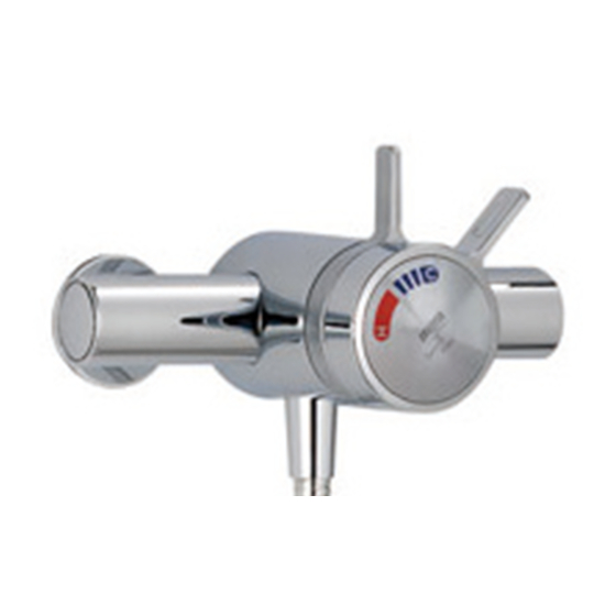
- Page 1 For SPARES, ADVICE or REPAIRS Please call us on 0844 571 5000 (UK Only) MIRA SELECT THERMOSTATIC MIXER INSTALLATION & USER GUIDE These instructions must be left with the user.
-
Page 2: Table Of Contents
Guarantee Having done so, keep it handy for future Recommended Usage reference. Safety Warnings The Mira Select thermostatic mixer is a shower Pack Contents control with separate flow and temperature Specifications controls. Installation... -
Page 3: Patents And Design Registration
3. Pass on this guide in the event of change of ownership of the installation site. For non-domestic installations, Mira Showers guarantee the Mira Select against any defect in 4. Follow all warnings, cautions and instructions materials or workmanship for a period of one year contained in this guide. -
Page 4: Pack Contents
Tick the appropriate boxes to familiarise yourself with the part names and to confirm that all of the parts are included. Mira Select Exposed 1 x Mira Select Shower Control (attached to the Building-in Shroud) 1 x Control Assembly 1 x Mira Select Shower Control... -
Page 5: Specifications
Note! For gravity fed or other low pressure Typical Flow Rates on Low Pressure Systems systems do not fit the outlet flow regulator. • (0.1 bar to 1 bar) - Mira Select with Mira For optimum performance supplies should be Fittings: nominally equal. - Page 6 Dimensions Ø56 149 - 154 67 - 85 Building-in Depth Ø183 All dimensions in mm...
-
Page 7: Installation
5. Pipework dead-legs should be kept to a INSTALLATION minimum. 6. Decide on a suitable position for the mixer. Suitable Plumbing Systems The position of the mixer and the shower fittings must provide a minimum gap of 25 mm Gravity Fed: between the spill-over level of the shower tray/ The thermostatic mixer must be fed from a cold bath and the showerhead (refer to illustration). -
Page 8: Installation Methods
Installation Methods For installation into a solid wall or stud partition using the securing brackets, refer to section: The Exposed Select Thermostatic Mixer can be ‘Built-in Thermostatic Mixer, 1. Solid Wall or installed with rear, rising or falling supply inlets. -
Page 9: Exposed Thermostatic Mixer
Exposed Thermostatic Mixer Ø32 mm x 10 mm depth for Concealing Plates 1. Rear Entry Supplies (rising or Backplate falling concealed pipework) Cold 13 mm from 1. Use the installation template to mark the finished wall positions of the holes for the backplate and surface the pipe centres. - Page 10 2. Rising or Falling Supplies 11. Tighten the compression nuts onto the elbows with a suitable spanner. 1. Loosen the grubscrew on each elbow using Caution! Take care not to damage the chrome the 2.5 mm hexagon key (supplied) and rotate surfaces.
- Page 11 4. Using the installation template as a guide, set 11. Tighten the grubscrew to secure the mixing the pipe centres 35 mm from the finished wall valve to the backplate. and mark the pipe positions. 5. Fit the supply pipework (Hot - Left, Cold - Right).
-
Page 12: Built-In Thermostatic Mixer
Built-in Thermostatic Mixer Alternative Pipe Outlet Pipe BIR Layouts 1. Solid Wall or Stud Partition (Using Securing Brackets - Mount- ing off Front Face of Wall) Outlet Pipe BIV Outlet Pipe BIV 1. Determine the route for the hot and cold supply pipework and for the outlet pipework. - Page 13 12.Connect the outlet pipework and install the 7. Secure the securing brackets to the mixing RAC assembly or BIR assembly, before valve with the bracket screws. continuing with the installation of the mixing Important! Make sure that the correct holes valve.
- Page 14 2. Solid Wall or Stud Partition 3. Make sure that the mixing valve is level, central in the hole and square to the finished wall (Using Rear Fixing Points on the surface. This is to make sure that the control Thermostatic Mixer) assembly will fit correctly.
- Page 15 3. Laminated Panel M5 Fixing Hole Backplate (Using Securing Brackets - Mount- Securing Hole ing on Rear Face of Wall) Filter Plug Note! For laminated panels the mixing valve must be positioned from the rear of the panel. Panel thickness must be between 4 and 12 mm. (If a thicker panel is used, it will be necessary to recess the securing brackets into the rear of the panel.)
- Page 16 8. Fit the hot and cold supply pipes (hot - left, cold - right) and tighten the compression nuts. Caution! Make sure that the olives are fitted and all pipework is flushed through before connecting to the mixing valve. Outlet Pipe to Fittings Cold 9.
-
Page 17: Rac Assembly
11. For stud partition installations with access Mira Energise RAC Mira Select RAC to the rear of the partition continue with instruction 5. 5. Secure the building-in shroud to the mixing Mira Energise RAC: valve using the two building-in shroud screws 1. - Page 18 9. Mark the positions of the two RAC backplate 16. Fit the two wall plugs supplied and secure fixing holes and drill two Ø5.5 mm holes. the wallplate to the wall with the two wallplate screws. Caution! Make sure that you do not drill into pipework in the wall.
- Page 19 Assembly’. tightening the nut, fit the retaining ring over the backplate nut making sure the slots engage Mira Select RAC: with the screws on the backplate, hold the 1. Before the RAC assembly can be fitted you retaining ring with a wrench while tightening must have first installed your built-in shower the backplate nut.
- Page 20 4. Determine the finished wall position (e.g. tile 9. Push the elbow fully into the backplate and thickness). Turn off the water supply, carefully rotate it clockwise, a ‘click’ will indicate when uncap the brass nipple and, if necessary, cut to it is locked.
-
Page 21: Control Assembly (Built-In Model)
Control Assembly (Built-in Model) 5. Locate the flow control lever over the control assembly and push firmly into place. 1. Unscrew the grubscrew and pull off the 6. Fit the bearing onto the flow lever. temperature control knob, bearing and flow Note! Align the bearing with the cutouts on the control lever. -
Page 22: Reversed Inlet Supplies
Reversed Inlet Supplies Thermostatic Cartridge The Mira Select thermostatic mixer is supplied ‘O’ Key with inlet connections Hot - Left, Cold - Right and Outlet - Bottom (exposed models), Outlet - Top Flow Lever Adaptor (built-in models) as standard. If the hot and cold... - Page 23 Built-in Model: 7. Rotate the thermostatic cartridge 180°. 8. Make sure that the two inlet seals are fitted 1. Isolate the hot and cold water supplies and and carefully push the thermostatic cartridge operate the flow control lever to relieve back into the mixing valve, aligning the lugs pressure and drain any residual water.
-
Page 24: Commissioning
6. Refit and secure the temperature control COMMISSIONING knob. 7. Check that the showering temperature is Maximum Temperature Setting correct. If the correct temperature setting cannot be achieved, refer to section: ‘Fault Before using the shower the maximum temperature Diagnosis’. must be checked to make sure that it is at a safe level. -
Page 25: User Maintenance
Symptom: USER MAINTENANCE • Noise from mixer valve If you require a Mira trained service engineer or Cause Rectification: • agent, refer to section: ‘Customer Services’. Check that the pressures are not inbalanced or in excess of the specifications for the Fault Diagnosis product. -
Page 26: Inlet Filters
Inlet Filters Backplate The inlet filters should be checked and cleaned Concealing Plate as necessary every 12 months. Note! The inlet filters must not be removed except Flow Control for cleaning. If the mixing valve is operated without Lever the inlet filters fitted, the warranty on the product will be void. -
Page 27: Spare Parts
SPARE PARTS Exposed Thermostatic Mixer 090.95 Pipe concealing plate (x 2) 1062476 Backplate 1062477 Filter Pack (x 2) 1062478 Elbow Connector Pack 1062479 Outlet Connector Pack 1592.080 Handle Pack 1592.081 Handle Adaptor Pack 1592.082 Elbow Assembly 1592.083 Adjustable Inlet 1592.084 Filter Cap (x 2) 1592.085 Seal Pack (identified ‘A’) -
Page 28: Built-In Thermostatic Mixer
Built-in Thermostatic Mixer 411.22 Select RAC Mounting Pack 411.66 Brass Nipple 413.57 Select RAC Shroud (chrome) 450.20 Energise RAC Mounting Pack 1592.086 Flow Lever Adaptor Pack 1592.087 Concealing Plate Assembly 1592.088 Handle Pack 1592.231 ‘O’ Key 1595.035 Energise RAC Shroud (chrome) 1595.036... -
Page 29: Accessories
ACCESSORIES Genuine Mira accessories can be purchased direct from Customers Services (our contact details can be found on the back cover of this guide) or from approved stockists or merchants. Eco Showerhead Everclear Showerhead Wall Mounted Soap Dish White - 2.1668.001 White - 2.1616.030... -
Page 30: Notes
NOTES... - Page 31 NOTES...
-
Page 32: Customer Service
The product must be installed and maintained in Spares and Accessories - We hold the largest accordance with the instructions given in this user stocks of genuine Mira spares and accessories. guide. Contact us for a price or visit our website to...
Need help?
Do you have a question about the SELECT and is the answer not in the manual?
Questions and answers