
Related Manuals for Mira Select


Summary of Contents for Mira Select
- Page 1 MIRA SELECT THERMOSTATIC MIXER Installation and User Guide These instructions must be left with the user.
-
Page 2: Table Of Contents
CONTENTS Introduction ..................... 3 Patents and Design Registration ............3 Safety : Warnings ..................4 Pack Contents ..................5 Dimensions ....................7 Specifi cations ..................8 Installation Requirements ..............10 Installation ..................... 12 General ....................12 Installation Methods ................13 Exposed Thermostatic Mixer .............. -
Page 3: Introduction
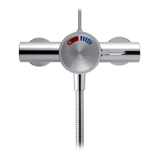
INTRODUCTION Thank you for purchasing a quality Mira product. To enjoy the full potential of your new product, please take time to read this guide thoroughly. Having done so, keep it handy for future reference. The Mira Select Thermostatic Mixer is a thermostatic Shower Control with separate fl... -
Page 4: Safety : Warnings
SAFETY : WARNINGS This Mira Select Thermostatic Mixer is precision engineered and should give continued safe and controlled performance, provided: It is installed, commissioned, operated and maintained in accordance with the manufacturer’s recommendations. Periodic attention is given, when necessary, to maintain the product in good functional order. -
Page 5: Pack Contents
PACK CONTENTS Tick the appropriate boxes to familiarize yourself with the part names and to confi rm that the parts are included. Exposed Select Thermostatic Mixer 1 x Mira Select Shower Control 2 x Concealing Plates 2 x Compression Nuts 1 x “O”... - Page 6 Built-in Select Thermostatic Mixer 1 x Mira Select Shower Control 1 x Control Assembly (attached to the Building-in Shroud) 3 x Compression 3 x Olives 1 x “O” Key Nuts 1 x Hexagon Key, 2 x Wall Plugs 1 x Flow Regulator, 2.5 mm...
-
Page 7: Dimensions
DIMENSIONS Exposed Select Thermostatic Mixer 149 - 154 Ø71 Ø56 Built-in Select Thermostatic Mixer Ø183 67 - 85 Building-in Depth All dimensions are in mm. -
Page 8: Specifi Cations
SPECIFICATIONS Operating Parameters For Type 2 valves, the supply conditions specifi ed in section: “Type 2 Valves - Application” take precedence over the operating parameters which follow. Pressures Maximum Static Pressure: 10 bar. Maximum Maintained Pressure: 5 bar. Minimum Maintained Pressure (Gas Water Heater): 1.0 bar. Minimum Maintained Pressure (Gravity System): 0.1 bar. - Page 9 Flow Rates Typical Flow Rates on Low Pressure Systems (0.1 bar to 1 bar) - Mira Select with Mira Select Adjustable Fittings or Rigid Head: Supply Pressure (bar) Typical Flow Rates on High Pressure Systems (1 bar to 5 bar, with 12 Litre/Min. Flow Regulator fi...
-
Page 10: Installation Requirements
Tempering Valve Overfl ow Indicator Mini Expansion Vessel Pressure Reducing Valve The Mira Select Thermostatic Mixer is compatible with the following systems: Gravity fed system The Shower Control MUST be fed from a cold water cistern and hot water cylinder providing nominally equal pressures. - Page 11 Unvented mains pressure system The Shower Control can be installed with an unvented stored hot water cylinder. Note! We recommend the use of a 12 L/Min. Outlet Flow Regulator (supplied). Mains pressurised instantaneous hot water system (thermal store) The Shower Control can be installed with systems of this type that have balanced pressures.
-
Page 12: Installation
INSTALLATION General The installation must be carried out in accordance with these instructions, and must be conducted by designated, qualifi ed and competent personnel. The installation must comply with the “Water Supply Regulations 1999 (Water Fittings)” or any particular regulations and practices as specifi ed by the local water company or water undertakers. -
Page 13: Installation Methods
Rear Entry Supplies Installation Methods Exposed Select Thermostatic Mixer The Exposed Select Mixer can be installed with rear, rising or falling supply inlets. The exposed model has inlet elbows which adjust between 149 mm - 154 mm. This feature assists the installation onto misaligned pipework. -
Page 14: Exposed Thermostatic Mixer
Exposed Thermostatic Mixer 1. Rear Entry Supplies (rising or falling concealed pipework) 1.1 Use the Installation Template to mark the positions of the holes for the Backplate and the pipe centres. Note! Allow a minimum of 150 mm either side of the unit, to allow access to the hot and cold Inlet Filters for servicing. - Page 15 1.6 Loosen the Grubscrew with the 2.5 mm Hexagon Key (supplied) and remove the Backplate from the unit. 1.7 Secure the Backplate to the wall using the Screws (supplied). 1.8 Fit the Concealing Plates. Note! Apply silicone sealant to the back face of the fl ange. Caution! It is essential at this point that the supply pipework is thoroughly fl...
-
Page 16: Rising Or Falling Supplies
2. Rising or Falling Supplies 2.1 Loosen the Grubscrew on each Elbow using the 2.5 mm Hexagon Key (supplied) and rotate the Elbow 90° as required. Retighten the Grubscrews. 2.2 Use the Installation Template to mark the positions of the fi xing holes for the Backplate. - Page 17 2.5 Fit the supply pipework (Hot - Left, Cold - Right). Note! If the connections are reversed, complete the installation then refer to section: “Reversed Inlet Supplies” before commissioning. 2.6 Loosen the Grubscrew with the 2.5 mm Hexagon Key (supplied) and remove the Backplate from the Mixer.
-
Page 18: Built-In Thermostatic Mixer
Built-in Thermostatic Mixer 1. Solid Wall or Stud Partition (Using Securing Brackets - Mounting off Front Face of Wall) 1.1 Determine the route for the hot and cold supply pipework and for the outlet pipework. When connecting Shroud to the BIV Shower Fittings it is Screws recommended that the outlet be (retain for... - Page 19 1.7 Fit the Securing Brackets to the unit Countersunk Fixing Hole with the Bracket Screws. Rotate for Suitable Important! Make sure that the Fixing Point correct holes are used, otherwise the Backplate cannot be fi tted. Rear Fixing Point Note! The Securing Brackets can be rotated for suitable fi...
- Page 20 1.12 Connect the outlet pipework, leaving Finished Wall Backnut Surface enough pipe to connect a 1/2” BSP (not supplied) female fitting (not supplied) to the Right Angle Connector (RAC) assembly. 20 to 22 mm 20 to 22 mm 1.13 When the 1/2” BSP female fitting and brass nipple have been fi...
- Page 21 1.18 Apply liquid sealant or PTFE tape to Nipple Foam Wallplate the exposed end of the Brass Nipple. Seal Screw the Mounting Bush on until the Mounting Bush Wallplate is loosely clamped against the wall. Then rotate the Wallplate Arrow and position as shown to align the arrow and release slot.
-
Page 22: Solid Wall Or Stud Partition (Using Rear Fixing Points On The Thermostatic Mixer)
2. Solid Wall or Stud Partition (Using Rear Fixing Points on the Thermostatic Mixer) Finished Wall 2.1 Refer to section: “1. Solid Wall or Surface Stud Partition (Using Securing Brackets - Mounting off Front Face of Wall)” and follow steps 1.1 to 1.4. - Page 23 2.3 Make sure that the unit is level, Outlet Pipe to Fittings central in the hole and square to the fi nished wall surface. This is to make sure the chrome trim and control handles will fi t correctly. Then mark the positions of the Fixing Screw holes on the wall.
-
Page 24: Laminated Panel
3. Laminated Panel (Using Securing Brackets - Mounting on Rear Face of Wall) Note! For laminated panels the unit must be positioned from the rear of the panel. Panel thickness must be between 4 and 12 mm. (If a thicker panel is used, it will be necessary to recess the Securing Brackets into the rear of the panel.) Important! Make sure that there is a minimum clearance of 64 mm behind the laminated panel to accommodate the unit. - Page 25 3.6 Drill the two 5.5 mm holes for the fi xing positions (countersink the holes at the front). 3.7 Secure the unit with the M5 x 40 mm screws as shown. 3.8 Fit the hot and cold supply pipes M5 x 40 mm (hot - left, cold - right) and tighten Fixing Screws the compression nuts.
- Page 26 3.13 Apply liquid sealant or PTFE tape to Nipple Foam Wallplate the exposed end of the Brass Nipple. Seal Screw the Mounting Bush on until the Mounting Bush Wallplate is loosely clamped against the wall. Then rotate the Wallplate Arrow and position as shown to align the arrow and release slot.
-
Page 27: Control Assembly (Built-In Model)
Control Assembly (Built-in Model) Backplate Concealing Plate Flow Lever Bearing Temperature Control Carefully separate the control Attach the Backplate using the assembly as shown. two Shroud Screws removed previously. Tighten the screws until the foam seal is compressed against the fi nished wall. -
Page 28: Reversed Inlet Supplies
REVERSED INLET SUPPLIES The Mira Select Thermostatic Mixer is supplied with inlet connections Hot - Left, Cold - Right and Bottom - Outlet as standard. If the hot and cold water supply pipes have been reversed during installation, the Thermostatic Cartridge must be removed and rotated 180°. - Page 29 Exposed Model Flow Control Lever Bearing Temperature Control Handle ‘O’ Key “B” “A” Cartridge Seal Built-in Model “B” Concealing Plate Backplate ‘O’ Key Cartridge Seal...
-
Page 30: Commissioning
COMMISSIONING Maximum Temperature Setting Before using the shower, the maximum temperature level must be checked to make sure that it is safe. It has been preset to approximately 43°C at the factory, but due to variations in site conditions the maximum temperature may need adjustment. Note! Make sure that the hot water temperature is at least 55°C and that there is a suffi... -
Page 31: Operation
OPERATION Shower Control (Exposed and Built-in Controls) Note! The shower performance may be affected if other water appliances are operated whilst the shower is in use. Turn the Flow Lever anticlockwise to the preset maximum fl ow Turn the Temperature Control Handle clockwise to decrease the temperature and anticlockwise to the preset... -
Page 32: Fault Diagnosis
FAULT DIAGNOSIS Symptom Cause / Rectifi cation Only hot or cold Inlets reversed (hot supply to cold supply). Refer water from the to section: “Reversed Inlet Supplies” for further outlet. details. No hot water reaching the unit. Check the Filters for any blockage. I n s t a l l a t i o n c o n d i t i o n s o u t s i d e o p e r a t i n g parameters: refer to sections: “Specifi... -
Page 33: Maintenance
Filters” for further details. If a malfunction occurs with the Thermostatic Cartridge, this will necessitate a complete cartridge replacement. Note! The cartridge contains no internally serviceable parts. If you require a Mira trained engineer or agent, then refer to section: “Customer Service” on the back of this guide. Lubricants Silicone based lubricants must only be used on the rubber seals. - Page 34 Start Measure and record supply temperatures and pressures, making sure that they are within the valve specifi cation. Measure and record blend temperature (Tb) and fl ow rate. fl ow rate fallen Check and clean checkvalves, signifi cantly or fallen below strainers and outlets.
- Page 35 Inlet Filters The Inlet Filters should be checked and cleaned as necessary every 12 months. Note! The Inlet Filters must not be removed except for cleaning. If the unit is operated without the Inlet Filters fi tted, the warranty on the product will be void. Exposed Models Isolate the hot and cold water supplies and operate the Flow Control Lever to drain any residual water.
- Page 36 Built-in Models Isolate the hot and cold water supplies and operate the Flow Control Lever to drain any residual water. Loosen the Grubscrew to remove the Temperature Control Handle. Then remove the Flow Control Lever. Carefully unclip the Concealing Plate from the Backplate. Note! Use a suitable screwdriver in the cutout to assist separation.
-
Page 37: Type 2 Valves
TYPE 2 VALVES Application The approved designations for Type 2 valves are as follows: Model Designation Code Mira Select HP-S / LP-S The permitted application details are: Operating Mixed Water Designation Application Pressure Range Temperature † °C HP-S High Pressure Shower 41 °C maximum... -
Page 38: Spare Parts
SPARE PARTS Exposed Select Thermostatic Mixer 090.95 Pipe concealing plate (x 2) 1062476 Backplate 1062477 Filter Pack (x 2) 1062478 Elbow Connector Pack 1062479 Outlet Connector Pack 1592.080 Handle Pack 1592.081 Handle Adaptor Pack 1592.082 Elbow Assembly 1592.083 Adjustable Inlet 1592.084... - Page 39 Built-in Select Thermostatic Mixer 411.22 RAC Mounting Pack 411.66 Brass Nipple 413.57 RAC Shroud-chrome 1592.086 Flow Lever Adaptor Pack 1592.087 Concealing Plate Assembly 1592.088 Handle Pack 1592.231 ‘O’ Key 1595.036 Temperature Hub Assembly 1595.039 Cartridge Assembly 1595.046 Seal Pack (identifi ed ‘A’) 1595.066...
-
Page 40: Customer Service
CUSTOMER SERVICE 1066764-W2-B (1592) (B92F, B92G) © Kohler Mira Limited, February 2007...
Need help?
Do you have a question about the Select and is the answer not in the manual?
Questions and answers