Advertisement
Quick Links
Installation & Maintenance Instructions
IMPORTANT:
See separate solenoid installation and
maintenance instructions for information on: Wiring, Sole
noid Temperature, Causes of Improper Operation, and Coil
or Solenoid Replacement.
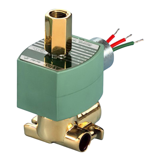
DESCRIPTION
Series 8317 V alves are direct acting, packless, 3-way solenoid valves.
Valve bodies are either brass or stainless steel with integral seats. A
core, disc, spring assembly and diaphragm are the only moving parts.
Valves may be provided with a general purpose/watertight, open-
frame or watertight/explosionproof solenoids.
OPERATION
The solenoid pilots the quick exhaust" diaphragm by using the un
balanced pressure principle. When the pressure orifice is open, the
main and pilot exhaust orifices are closed. When the pressure orifice
is closed, the main and pilot exhaust orifices are open.
Normally Closed:
Solenoid De-energized: Flow is from Cylinder 1" to Main Exhaust
4". Pilot Exhaust is open. Pressure 2" is closed.
Solenoid Energized: Flow is from Pressure 2" to Cylinder 1", Main
Exhaust 4" and Pilot Exhaust 3"are closed.
Universal:
Pressure at 2": Refer to Normally Closed above.
Pressure at 3": Refer to Normally Open above.
Universal construction is interchangeable with Normally Closed in
the field by merely changing pipe connections.
IMPORTANT: A minimum operating pressure differential
of 5 psi on Air, Gas and Water and 10 psi on Hydraulic oil
(300 S.S.U.) is required.
NORMALLY CLOSED
DE-ENERGIZED
PILOT
3
EXH
2
4
PRESS
MAIN EXH
UNIVERSAL (PRESSURE AT 2")
DE-ENERGIZED
ENERGIZED
3
PILOT
PILOT
3
EXH
EXH
1
CYL
2
2
4
4
PRESS
PRESS
MAIN EXH
MAIN EXH
NOTE: Port markings 1, 2, 3 and 4 correspond directly to A, B, C and
C2.
50 Hanover Road, Florham Park, New Jersey 07932 www.ascovalve.com
3-WAY QUICK EXHAUST SOLENOID VALVES
NORMALLY CLOSED AND UNIVERSAL OPERATION
ENERGIZED
PILOT
3
EXH
1
1
CYL
CYL
2
4
PRESS
MAIN EXH
UNIVERSAL
(PRESSURE AT 3")
DE-ENERGIZED
ENERGIZED
3
PRESS
PRESS
3
1
1
CYL
CYL
2
2
PILOT
4
PILOT
EXH
EXH
MAIN EXH
MAIN EXH
1/4I NPT
Check nameplate and solenoid marking for correct catalog number,
pressure, voltage, frequency, and service. Never apply incompatible
fluids or exceed pressure rating of the valve. Installation and valve
maintenance to be performed by qualified personnel.
Future Service Considerations.
Provision should be made for performing seat leakage, external leak
age, and operational tests on the valve with a nonhazardous,noncom
bustible fluid after disassembly and reassembly.
Temperature Limitations
Valves with design change letter K" or P" within the catalog num
ber (example: 8317K007) have a maximum fluid temperature of
180_F. Refer to separate solenoid Installation and Maintenance In
structions for maximum ambient temperature.
Positioning
This valve is designed to perform properly when mounted in any posi
tion. However, for optimum life and performance, the solenoid
should be mounted vertically and upright to reduce the possibility of
foreign matter accumulating in the solenoid base sub-assembly area.
Piping
The pressure and exhaust lines must be connected as indicated in the
flow diagram for the particular application. Full size piping must be
used.
On Normally Closed Valves, the 3" connection is a Pilot Exhaust and
may be connected to a Common Exhaust with the 4" connection.
IMPORTANT: Pilot Exhaust 3" on Normally Closed form
must be connected at the installation into the piping to the
Main Exhaust 4" when controlling fluids such as liquids or
flammable gases that are not permissible to exhaust to at
mosphere.
Connect piping to valve according to markings on valve body. Apply pipe
compound sparingly to male pipe threads only. If applied to valve
threads, the compound may enter the valve and cause operational diffi
culty. Avoid pipe strain by properly supporting and aligning piping.
When tightening the pipe, do not use valve or solenoid as a lever, Locate
wrenches applied to valve body or piping as close as possible to con
nection point.
IMPORTANT: To protect the solenoid valve, install a strain
er or filter suitable for the service involved, in the inlet side
as close to the valve as possible. Clean periodically depend
ing on service conditions. See ASCO Series 8600, 8601 and
1
8602 for strainers.
CYL
4
SERIES
8317
I&M No.V7536
INSTALLATION
Page 1 of 3
All Rights Reserved.
E176965
Advertisement

Related Manuals for Asco RedHat 8317 Series


Summary of Contents for Asco RedHat 8317 Series
- Page 1 PRESS PRESS er or filter suitable for the service involved, in the inlet side as close to the valve as possible. Clean periodically depend ing on service conditions. See ASCO Series 8600, 8601 and 8602 for strainers. PILOT PILOT PRESS...
- Page 2 All solenoid valves should be cleaned periodically. The time between Replace worn or damaged parts with a complete ASCO Re build Kit for best results. cleanings will vary depending on the medium and service conditions.
- Page 3 175 ± 25 19,8 ± 2,8 seat/end plug 125 ± 20 14,1 ± 2,3 Indicates Parts Supplied solenoid base In ASCO Rebuild Kits sub-assembly core assembly core spring bonnet gasket valve body diaphragm end plug gasket seat/end plug Figure 1.
Need help?
Do you have a question about the RedHat 8317 Series and is the answer not in the manual?
Questions and answers