
Related Manuals for Gecko Compact


Summary of Contents for Gecko Compact
- Page 1 Gecko Seismographs, Accelerographs Recorders, Vibration Monitors For all models: Compact, Rugged, Blast, Tremor, Prism, SMA & SMA-HR 141 Palmer Street, Richmond VIC 3121 Australia T:+61 3 8420 8940 sales@src.com.au...
- Page 2 In the Gecko, we have reinvented the modern digital seismograph. The low cost of flash memory means you can save weeks, months, even years of continuous data on a single memory card.
-
Page 3: Table Of Contents
Table of Contents Getting Started ................. 1 Setting up your recorder ..................1 The User Interface ....................2 Menu Map ......................3 The Home Screen ................4 Status Screen Loop – Right Button ..............4 Realtime Data Loop – Up Button ................5 Sensor Signal .................... - Page 4 Ports & Wiring ................24 Power connector ....................24 Alarm & Communications port ................25 4D Sensor port (2018 Compact & Rugged) ............25 1D Sensor port (mid-2019 Blast & SMA) ............25 Register your Gecko ................ 26 Warranty ..................26 Extended warranty ....................
-
Page 5: Getting Started
GPS socket until finger-tight. The Gecko Compact and Rugged is supplied with a sensor plug which you can attach to your sensor cable. You can find the wiring diagram at the end of this manual. Align the keyed plug with the socket and push it on, locking it in place with the bayonet-style collar. -
Page 6: The User Interface
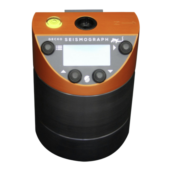
The User Interface The Gecko does not require a computer to control it. All recorder settings are accessible through the LCD and are modified using the four control buttons. Gecko Compact (above) S E I S M O G R A P H... -
Page 7: Menu Map
*1 will not appear on 3-channel models 12,356 *2 "1D Sensor Info" will show here for 4-channel models 0.1234567 mm/s *3 will only appear on Gecko Compact & Rugged 11.1234567 mm/s 80.2123546 dB *4 will only appear if sensor has calibration function max 101.1234567 dB... -
Page 8: The Home Screen
Status Screen Loop – Right Button Version 4 of the Gecko firmware expands the status line to several status pages. These are shown on the Menu Map within the blue area. Press the Right button to scroll through them, or press the Menu/Left button to return to the Home screen. -
Page 9: Realtime Data Loop - Up Button
-0.0011021 mm/s next 2 seconds. If you have a 4-channel Gecko, the date and time line will not be shown, with channel O appearing at the bottom with its live sensor units values shown as per the settings. Vector Sum The next screen Up shows the live vector sum of the 3D sensor, and holds the peak value. -
Page 10: The Main Menu
Unmount SD card In version 3.2 of the Gecko firmware we removed the option to stop and start data sampling. Data is being sampled at all times, whether an SD card is present or not, because data can be telemetered without an SD card. -
Page 11: Data Storage
SD cards can be used in the Gecko if they are pre-formatted as FAT (not exFAT). To remove the card from a Gecko Compact 3ch (above, left) slide open the SD card cover and press in the SD card to eject it. The SD card faces up, and it cannot be inserted upside- down. -
Page 12: Station Code
Location ID. This station code (default is GECKO) can be up to 5 characters long and can only contain uppercase letters and numbers. If you wish to use less than 5 characters, end the code with blank space character. -
Page 13: Sample Rate
Band Code, the second letter indicates the Instrument Code, and the third letter is the Orientation Code. Detailed information on this standard can be found here: https://ds.iris.edu/ds/nodes/dmc/data/formats/seed-channel-naming/ The Gecko will set the first letter of the channel name based on the sample rate: • B: 40 sps •... -
Page 14: Channels To Store
Disabling a channel in telemetry will not disable that channel in the “Channels to Store” settings. Sensor Setup This section of the user manual applies to Gecko Compact, Rugged, Blast and SMA models only. For all other models, skip ahead to the Input Amplifier section. 3D Sensor... - Page 15 Select a Sensor The Gecko has a range of popular sensors settings preloaded into the menu to save users the trouble of entering all of the parameters that allow the data to be displayed in engineering units (e.g. mm/s, g, mm, dB, rad/s, etc.) rather than recorder counts.
- Page 16 V/g for convenience as most sensors are specified in this manner. The Gecko can automatically set the zero signal level after the recorder is powered up. If your sensor performs a self-test on start-up, or requires some time before it settles, use the...
-
Page 17: External 1D Sensor
0V to +5V, where the zero level normally sits at +2.5V. In this case, much of the -20V to +20V input range of the Gecko is wasted. Running the Gecko’s Input Amplifier at x4 would effectively stretch the 0-5V to 0-20V, but you would still only be using the upper half of the Gecko’s dynamic range. -
Page 18: Input Amplifier
Gecko - e.g. ±5V IEPE accelerometers or ±4V MEMS accelerometers (as used in the Gecko SMA), could use a gain of x4 to stretch those output to ±20V or ±16V respectively to record at higher resolution. Note that ground offsets will also be amplified. -
Page 19: Trigger & Alarm
System Alerts The Gecko logs the trigger time to a text file that can be used to help you find the data in the continuous archive. This “trig.txt” file is located in the top level folder of the SD card. -
Page 20: Sta/Lta Triggering
STA/LTA Triggering By default the STA/LTA trigger process is OFF. Toggle this ON/OFF using the Right button. STA/LTA Triggering Enable: Off > Threshold STA window size LTA window size Filter: 2-20Hz Channel: Z+N+E The Short Term Average (STA) signal level divided by the Long Term Average (LTA) signal level produces a ratio indicating how much above-average signal is occurring. -
Page 21: Alarm Outputs
Alarm #1 is activated, and to pin 5 for Alarm #2, for the alarm duration. By default the Gecko’s positive power is hard-wired to pin 6, but on request we can modify the hardware to make pin 6 a user input line that switches to the Alarm outputs. If this modification is done, the switching circuit is rated to 0.13A at 50VAC or 50VDC, but we can... -
Page 22: On-Screen Alerts
(e.g. voltage returns to normal) and then becomes true again. The Gecko uses a data ring buffer, which means it will overwrite old data with new data when the memory card has only 2% storage remaining. A Low Memory alert will be raised when less than 4% of storage remains. -
Page 23: Mode
SD card as they become available. The time period before or after the trigger time to be extracted is defined by the user in the remote server software. When telemetry mode is set to Off the Gecko will not attempt to start a serial connection. Device This setting defines the type of communication device connected to the Gecko’s... -
Page 24: Settings File
Settings File You can save the configuration of your Gecko to a text file. Simply enter the “Settings File” menu located at the bottom of the main menu. Configuration File Load Settings > Save Settings Reset to Factory Use the Right button to select the action. When saved, a file called “user-settings.dat” is written to the top level folder of the SD card. -
Page 25: Data Storage And Formats
Data Storage and Formats The Gecko stores continuous data to the SD card in a logical file hierarchy to make it easy to find the data you’re looking for, but it also stores some additional files that you may find useful. -
Page 26: The Root Directory
• settings.ss: also a text file, containing all of the current configuration settings of the Gecko. It is updated each time the user changes a setting. • user-settings.dat: the current configuration of the Gecko as written by the Load/Save Settings function described earlier •... -
Page 27: The Histogram Folder
= 0.00023062 (or 0.23062 mm/s) MiniSEED files Continuous data files in the Gecko are in MiniSEED format, which is a widely adopted international standard format for seismic data. You can find out more about this data format at the IRIS website: http://ds.iris.edu/ds/nodes/dmc/data/formats/miniseed/... -
Page 28: Upgrading The Gecko Firmware
After the upgrade the Rasbora.bin file remains in the root folder of the SD card so that the card can be used to upgrade other Gecko recorders, but it can be deleted from the folder at any time with no adverse effect on the Gecko. -
Page 29: Alarm & Communications Port
4D Sensor port (2018 Compact & Rugged) At left is a diagram of the pin connections of the Gecko sensor port. Looking at the wire- connection side of the supplied cable plug shows the same pin configuration. The function of each pin is listed in the table below the drawing. -
Page 30: Register Your Gecko
Register your Gecko We highly recommend registering your Gecko with us so that we can add you to our product update notification list. Simply email sales@src.com.au with your Gecko serial number and we will notify you when Gecko firmware updates and Waves software updates are available –... - Page 31 Appendices...
-
Page 32: Installing The Gecko Blast Or Sma
Appendix A Installing the Gecko Blast or SMA The Gecko Blast and SMA are designed to measure large vibrations. You can simply sit them on a surface to measure ground motion, but we recommend you bolt the sensors down. To install the Blast in soft soil, screw the three included spikes into the holes in the base, which may require you to unscrew the standard adjustable feet. -
Page 33: Gains, Range And Clip Levels
Loosen the upper locking nuts on the adjustable feet and screw the feet in or out until the bubble on top of the Gecko is centred indicating that the chassis is level. Screw the locking nuts up to the base of the Gecko so that the feet can no longer be adjusted. -
Page 34: Installing The Gecko Sma-Hr
Screw the supplied 8mm threaded rod into the anchor. After tightening, ensure the rod cannot be pulled out of the ground by hand. Using the central hole in the Gecko SMA-HR, slide the unit over the threaded rod. - Page 35 Loosen the upper locking nuts on the two adjustable feet and screw the feet in or out until the bubble on top of the Gecko is centred indicating that the chassis is level. Screw the locking nuts up to the base of the Gecko so that the feet can no longer be adjusted.
-
Page 36: Calibrating A Gecko Sma-Hr
Tremor will either be local earthquake monitoring (in which case you would orient the arrow on the lid of the Gecko to point North) or for local blast or vibration monitoring (in which case you may wish to orient the arrow to point towards the vibration source which will make the North channel a record of radial energy, which in turn makes the East channel a record of transverse motion. -
Page 37: Installing The Gecko Prism
Installing the Gecko Prism The Gecko Prism contains a very robust but very sensitive velocity sensor. Once the seismograph is powered on, be careful not to move the sensor. Pressing the buttons to control the unit should not send the sensor into a clipping condition. If you accidentally knock the sensor and the signal levels start clipping, simply turn the unit off for a second and then on again to quickly settle the sensor. -
Page 38: Internal Battery
Internal Battery When the optional internal Nickel Metal Hydride (NiMH) battery is fitted to the Gecko Rugged, Prism or SMA-HR, the Gecko power circuit will be set to cut power when the battery voltage drops too low to protect the battery. -
Page 39: Charge Regulator
Charge Regulator Rechargeable Nickel Metal Hydride (NiMH) batteries require a particular power delivery cycle for optimum charging and battery life. An unregulated power supply can provide a NiMH battery pack with charge, but without proper regulation the battery can become damaged from over-charging or over-heating. -
Page 40: Perle Iolan Ds1 Ethernet Adaptor
Appendix C Perle IOLAN DS1 Ethernet Adaptor If you need to stream your seismic data over a Local Area Network (LAN) or over the Internet in real time to a remote computer, an Ethernet adaptor is available for connection to the recorder’s communication port. Our free Kelunji Hub and Live Stream software is available for installation on your own remote Windows or Linux computer, or you can subscribe to our cloud data hosting service. -
Page 41: Change Ip Address Of The Ethernet Adaptor
Change IP address of the Ethernet adaptor When you log into the Ethernet adaptor, you’ll see the screen below. You will most likely need to change the IP address of the device to an address that is compatible with your LAN. Click on the “Network”... -
Page 42: Define Ip Address Of Kelunji Hub Computer
If you have enabled Telemetry via Ethernet in your Gecko, the Gecko will now connect to the Kelunji Hub application on the Host server, then automatically start streaming data. You can check the connection status on the Gecko Home screen by pressing the Right button until the Connection status message is displayed. - Page 43 Gecko Seismographs and Accelerographs Digitisers To Record Any Sensor GECKO COMPACT GECKO RUGGED Portable Vibration Sensors BLAST or SMA Professional Earthquake Sensors src.com.au SMA-HR TREMOR or PRISM...
Need help?
Do you have a question about the Compact and is the answer not in the manual?
Questions and answers