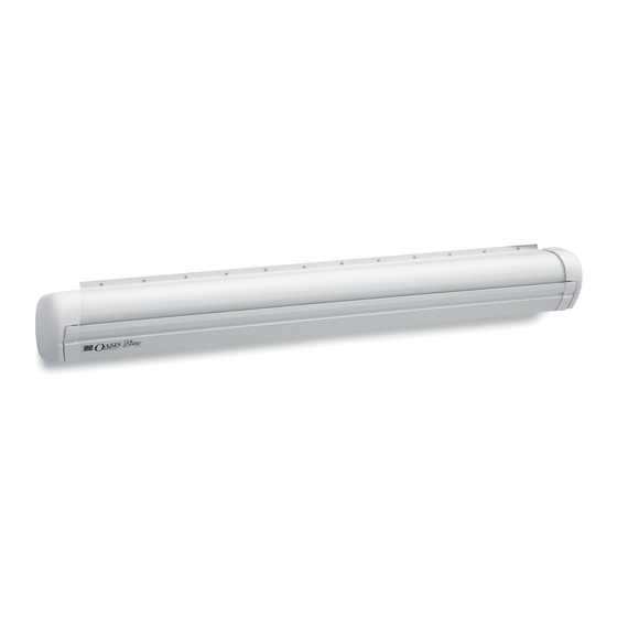
Summary of Contents for Dometic Weather Pro
- Page 1 DIAGNOSTIC SERVICE MANUAL REVISION: Form No. 3308058.019 8/04 (Replaces 3308058.001) ©2004 Dometic Corporation LaGrange, IN 46761...
-
Page 2: Table Of Contents
Contents PAGE NO. WeatherPro & Oasis Elite Symptom/Cause ........... 3 SECTION 1- Wiring .................. 4-6 12VDC Supply Wire ..............4 Wire From Control Box To Awning ........... 4 Wire Inside Hardware Channel (WeatherPro Only) ......4 Motor Connection & Motor ............... 5 Wire To Remote Switch .............. -
Page 3: Weatherpro & Oasis Elite Symptom/Cause
SYMPTOM CAUSE LOCATION 1. Awning will not open 1. 12VDC Supply Wire Section 1.1 2. Fuse Section 3.1.3 3. Ignition Interlock (WeatherPro) Section 1.7 & 3.1.7 4. Wiring/Connections Section 1.2, 1.3, 1.4.1, 1.5 & 9.1 5. Wind (WeatherPro) Section 2.1 & 3.3 6. -
Page 4: Section 1 Wiring
SECTION 1 WIRING 3307930 & 3309114 Control Box Kit Using 12VDC Supply Wire Universal MATE-N-LOK Soft Shell Connector 1.1.1 The 12VDC supply wire must be run from the 12VDC supply source to the Control Yellow (10) Yellow/White (9) Oasis WeatherPro Box. -
Page 5: Motor Connection & Motor
A standard telephone cable will not work. Cable can be checked with a Dometic 3107127.007 cable tester. If cable is found to be defective replace with a cable no longer than 18'. -
Page 6: Ignition Interlock Wire
It should be a 16 gauge wire. Make sure wire connections are tight and corrosion Note: Dometic uses two different control box configura- free. See FIGS. 1.1A & 1.7. tions for the WeatherPro Awnings. The first is part number 3307916 and has 6 molded rubber plug harnesses com- FIG. - Page 7 Cable to Wind Sensor 3307916 Control Box FIG. 3.4A (18 Foot Maximum) WeatherPro Rocker Switch WeatherPro T14 T15 T16 T17 T18 T19 T20 T12 T13 Remote Switch Green Open Yellow Green Brown Blue Brown White Blue Oasis Elite Remote Switch Close Yellow Brown...
-
Page 8: Control Box Rocker Switch
3.1.5 WeatherPro Remote Switch the Brown/White (pin 14) wire. You a. To check the WeatherPro (3307916 should hear another relay click and Control Box) remote switch connec- the volt meter should read (+) posi- tion (Brown, Green, & Yellow) wires tive 12 VDC (minimum). -
Page 9: Wiring Diagram
click is present switch is defective. Replace SECTION 5 Remote Key FOB switch. The remote key FOB is powered by a 12 VDC 3.3 Wind Sensor Toggle Switch type 23A battery. The operational range is up to The toggle switch turns the wind sensor feature 30 feet. -
Page 10: Section 6- Weatherpro Auxiliary Cable
Bolt must be reinstalled to prevent awning from Remove from opening during travel. Have awning serviced by a Both Ends Dometic Service Center or a qualified service tech- nician before attempting to open awning after this Awning Rail procedure has been performed. -
Page 11: Left Hand Torsion Removal
8.2.3 Extend or open the awning two revolu- Left Hand Torsion Removal tions of the FRTA. This will allow for re- moval of top brackets and the FTRA. 8.2.4 Pin the left hand torsion. See Section 8.3. Use extreme care. Springs under tension are 8.2.5 Disconnect the wire harness at the plug dangerous. -
Page 12: Right Hand Drive Assembly Removal
8.3.5 Remove Hex Head 1/4"-20 x 1/2" screw 8.5.2 Remove both torsions. See Sections 8.3 that attaches arm assembly to top cast- and 8.4 for drive assembly removal. ing. Lift casting out of arm assembly. 8.5.3 Roll the awning completely out on a clean 8.3.6 Clamp a Vice-Grip®... -
Page 13: Reinstall Fabric On Roller Tube
End Cap Guide on the roller tube. This should align 8.7.2 Dometic requires the use of the end cap the open channel with the slot in the guide to prevent damage to the fabric, end cap. -
Page 14: Left Hand Torsion Assembly Winding
8.8.5 Install right hand drive torsion a. New right hand drive torsions are shipped with the top casting and the stabilizer positioned for installation. If Severe injury can result from the rapid spin-of the torsion has been pre-installed it of the top casting. NEVER use bare hands to must be aligned before it is put into the handle a top casting under spring tension. -
Page 15: Section 9- Wiring Diagram
8.9.4 Remove Vise Grip® from top casting and insert into arm assembly. Replace Hex Head 1/4"-20 x 1/2" screw and tighten. Note: If awning is not installed on coach. Install per the WeatherPro installation instructions. 8.9.5 Remove 2-3/4" cotter pin and check op- eration of the awning. - Page 16 FIG. 9.1B 3307930 & 3309114 Yellow (10) Oasis Yellow/White (9) Control Box WeatherPro Elite Brown (15) Remote Switch Brown/White (14) Remote Switch Green (5) Green/White (4) Ignition Pink (3) Isolator Red (13) Blue or BlK/Wh (7) Black (8) Red/White (12) AMP 2-Pin WeatherPro Connector...


Need help?
Do you have a question about the Weather Pro and is the answer not in the manual?
Questions and answers