
Related Manuals for Scolmore Click Smart Series

Summary of Contents for Scolmore Click Smart Series
- Page 1 For the full Quick Install Guide interactive experience use Adobe PDF Reader on your Control Menu smart device Contents Wiring Accessories for a Smarter Home Smart Box & Application Installation & Control Manual (Rev1.1)
- Page 2 Prev Page Next Page Contents Installation Check List Before you begin Congratulations on purchasing the Click Smart Box (CSB040), an element of the Click Smart control system. This instruction manual provides information on installing and operating the smart box and applications. Only perform the Click Smart installation after becoming thoroughly familiar with this manual and the system functions.
-
Page 3: Table Of Contents
Prev Page Next Page Installation Check List Contents Smart Box Introduction What Is In The Box? ................... 5 Smart Box Installation ................5 Preparation ....................6 Receiver Information .................. 6 Operating System ..................6 Quick Installation Guide & Check List ............7 Application Installation Guide Pairing the Smart Box ................ - Page 4 Prev Page Next Page Contents Installation Check List Introduction With the CSB040 Click Smart Box connected to your router (Ethernet cable), it then enables you to control your Click Smart wireless control system by smart phone or tablet devices utilising the Click Smart application. The smart box communicates using the frequency 868MHz and enables the control of up to 40 Click Smart receivers from one location.
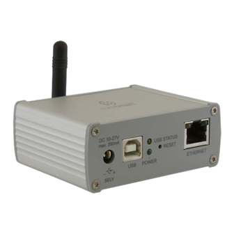
- Page 5 Prev Page Next Page Contents Installation Check List What Is In The Box - CSB040 1. Click Smart Box 2. 230V~ Plug In Adaptor 3. Ethernet Cable Smart Box Installation Connect the Smart Box to the power source and using the Ethernet cable connect it to your local router.
- Page 6 Prev Page Next Page Contents Installation Check List Preparation - Receiver Information To assist with the configuration of the application, ensure the receiver type, hexadecimal address and location is noted for each receiver installed on the installation sheet provided (example shown). Without the receiver type and correct hexadecimal address, the receiver details cannot be added to the application.
- Page 7 Prev Page Next Page Contents Preparation - Quick Installation Guide & Check List To assist in the setting up of the smart box and applications, we recommend the following process is followed. Installation Sheet (printed copy supplied) Document list of rooms, receivers, receiver type and receiver address page 6 Range Test Carry out range test, (a repeater RFRP-20/B may be required)
-
Page 8: Preparation
Prev Page Next Page Contents Installation Check List Application Installation Guide With the preparation completed, the application can Pairing The Smart Box be opened. The initial screen is a reminder to ensure the latest Add Rooms operating system update is running on the smart device. -
Page 9: Pairing The Smart Box
Prev Page Next Page Contents Installation Check List Application Guide - Pairing The Smart Box With the CSB040 smart box connected to the router, and the smart device (Phone Add Rooms or tablet) connected via Wi-Fi to the same router, the app will pair using DHCP connection. - Page 10 Prev Page Next Page Contents Installation Check List Application Guide - Adding ‘Rooms’ With ‘Rooms’ home screen shown, the list of room (location) names for the complete Pairing The Smart Box installation can be added. Select ‘ADD ROOM’ to enable the list of rooms on the installation sheet to be entered. Add/Assign Elements 1.
- Page 11 Prev Page Next Page Contents Installation Check List Application Guide - Adding & Assigning ‘Elements’ With ‘Elements’ home screen shown, the elements (receivers and related appliance) Pairing The Smart Box for the complete installation can be added and also assigned to its room (location). Select ‘ADD ELEMENTS’...
- Page 12 Prev Page Next Page Contents Installation Check List Application Guide - Adding & Assigning ‘Elements’ cont’d 4. With the address entered, select ‘Type of receiver’. Pairing The Smart Box From the drop down menu, select the installed receiver type, e.g. RFDEL-71B. Add Rooms 5.
- Page 13 Prev Page Next Page Contents Installation Check List Application Guide - Creating Scenes Creating scenes enables multiple elements (receivers) to be added with each element Pairing The Smart Box assigned its own function for that scene. With a single press all the set commands can be carried out.
- Page 14 Prev Page Next Page Contents Installation Check List Application Guide - Creating Scenes - continued 3a. Switching receiver selected. Pairing The Smart Box Android - The initial screen starts up with time delay settings (see below) with standard switching ‘On’ and ‘Off’. Add Rooms iOS - The initial screen starts up with the respective element selected icon, ‘On’...
- Page 15 Prev Page Next Page Contents Installation Check List Application Guide - Creating Scenes - continued 3b. Dimming receiver selected. Pairing The Smart Box A. The initial screen starts up with the dimming arc. Add Rooms Simply press or press and slide around the arc to set the required lighting level. Select back to save the setting and return back to the scene listing.
- Page 16 Prev Page Next Page Contents Installation Check List Application Guide - Creating Scenes - continued 3c. Shutter receiver selected. Pairing The Smart Box The initial screen starts up with the blind icon and receiver / appliance identification. Add Rooms The initial setting allows you to set ‘Up’ (open) or ‘Down’ (closed). Select ‘Next’...
-
Page 17: Settings Menus
Prev Page Next Page Contents Installation Check List Application ‘Settings’ Menus With the application guide completed, any additions or amendments to rooms, elements and scenes can be made by accessing the ‘Settings’ menu. The Settings menu is accessed by pressing the three vertical dots in the top right hand corner of the app. - Page 18 Prev Page Next Page Contents Installation Check List Settings Menu - Smart Box Settings With the smart box paired during initial the application guide setup, the paired smart box will be listed including its IP address and blue circle confirming its pairing. The ‘Smart Box Settings’...
- Page 19 Prev Page Next Page Contents Installation Check List Settings Menu - Smart Box Settings • Add If you know the IP address of the smart box it can be added manually along with its name. • Smart box pairing data Displays: •...
-
Page 20: Elements
Prev Page Next Page Contents Installation Check List Settings Menu - Elements Accessing ‘Elements’ from within the application enables the initial information Add Rooms entered to be amended or deleted or new elements/receivers to be added. From within the same menu time schedules can also be added. See page 26 more information on adding time schedules. -
Page 21: Rooms
Prev Page Next Page Contents Installation Check List Settings Menu - Rooms Accessing ‘Rooms’ from within the application enables the initial information entered Add Elements to be amended or deleted or new rooms/locations to be added. Select the room and the list of elements will appear. Where elements were previously assigned to the room will have a tick. -
Page 22: Scenes
Prev Page Next Page Contents Installation Check List Settings Menu - Scenes Accessing ‘Scenes’ from within the application enables the initial information entered Assign Switching to be amended or deleted or new scenes can be created. Select the scene and the list of elements will appear. Where elements were previously assigned to the scene will have a tick. - Page 23 Prev Page Next Page Contents Installation Check List Settings Menu - Scenes - Switching Receiver Functions Switching receiver selected. Assign Dimming Android - The initial screen starts up with time delay settings (see below) with standard switching ‘On’ and ‘Off’. Assign Shutter iOS - The initial screen starts up with the respective element selected icon, ‘On’...
- Page 24 Prev Page Next Page Contents Installation Check List Settings Menu - Scenes - Dimming Receiver Functions Dimming receiver selected. Assign Switching A. The initial screen starts up with the dimming arc. Simply press or press and slide around the arc to set the required lighting level. Select Assign Shutter back to save the setting and return back to the scene listing.
-
Page 25: Time Schedules
Prev Page Next Page Contents Installation Check List Settings Menu - Scenes - Shutter Receiver Functions 3c. Shutter receiver selected. Assign Switching The initial screen starts up with the blind icon and receiver / appliance identification. The initial setting allows you to set ‘Up’ (open) or ‘Down’ (closed). Assign Dimming Select ‘Next’... - Page 26 Prev Page Next Page Contents Installation Check List Settings Menu - Elements - Schedules Creating and activating time schedules enables selected elements to be automated Select Elements which in turn can provide additional security, e.g. simulated occupancy. The schedules programmed are stored by the smart box so once setup and activated the smart phone or tablet does not need to be connected to the router / Wi-Fi .
-
Page 27: Select Elements & Functions
Prev Page Next Page Contents Installation Check List Schedules - Create - Select Elements & Functions To create time schedules simply add the schedule name, select the smart box and the Schedules required elements (must be of the same function, e.g. all switching receivers). Assign Day &... - Page 28 Prev Page Next Page Contents Installation Check List Schedules - Create - Select Elements & Functions - cont’d Dimming elements / receivers: Schedules RFDA-71B, RFDEL-71B and RFDAC-71B Functions available: Four dimming levels (default 20, 50, 70 & 100%) allowing Assign Day & Times the desired level to be set for a specified time period.
-
Page 29: Assign Day, Times & Function
Prev Page Next Page Contents Installation Check List Schedules - Create - Assign Day, Times & Function Schedules Weekly overview screen Select Elements Select ‘New’ to open the input screen. Amend & Copy Activate Schedules Day, time and function input screen Dependant on the element type will depend on the input screen information displayed. -
Page 30: Activate
Prev Page Next Page Contents Installation Check List Schedules - Create - Assign Day, Times & Function cont’d Day, time and function input screen (switching elements) Schedules With the day, times and ‘ON’ function added, pressing save will then display the weekly overview screen with the time selection displaying on the time bar. - Page 31 Prev Page Next Page Contents Installation Check List Schedules - Create - Assign Day, Times & Function cont’d Day, time and function input screen (dimming elements) Schedules With the day, times and dimmed levels added, pressing save will then display the weekly overview screen with the time selection displaying on the time bar.
- Page 32 Prev Page Next Page Contents Installation Check List Schedules - Amend, Remove & Copy Amend & remove times set Schedules With the weekly overview screen open, press the coloured time bar which shows the ‘from’ and ‘to’ times. Slide up or down to adjust each time or press and ‘hold’ the opened time bar (fig.
- Page 33 Prev Page Next Page Contents Installation Check List Schedules - Activate Once time schedules have been setup, for them to operate automatically the ‘AUTO’ Schedules setting within each element must be enabled. To engage the ‘AUTO’ setting the element control screen must be accessed. Exit the settings menu and enter the room and element to enable.
- Page 34 Prev Page Next Page Contents Installation Check List Advanced Settings Advanced settings provides access to the following features: Settings Menu Menu Control Standard Design White Design • Receive firmware updates notification Notifications will be sent with regards updates for the smart box. •...
-
Page 35: Switching
Prev Page Next Page Contents Installation Check List Application Control The control menus enables rooms, scenes and elements to be easily selected with Control Switching the required element or scene then controlled. The initial screen displays the rooms with icons, swipe left and the scenes (if setup) are then displayed. -
Page 36: Dimming
Prev Page Next Page Contents Installation Check List Application Control - Switching The current status icon of the switching receiver is displayed. Control Control Dimming Control Shutter Control Scene Icon pale grey outline. Icon white outline. Icon with blue infill. Receiver element is Receiver element is Receiver element is... -
Page 37: Shutter
Prev Page Next Page Contents Installation Check List Application Control - Dimming The current status icon of the dimming receiver is displayed. Control Control Switching Control Shutter Control Scene Icon blue outline. Icon with blue infill. Icon with blue infill and Receiver element is Receiver element is white arc displayed. -
Page 38: Scenes
Prev Page Next Page Contents Installation Check List Application Control - Shutter The current status icon of the shutter receiver is displayed. Control Control Switching Control Dimming Control Scene Icon pale grey outline. Icon with white outline and Icon with blue infill and Receiver element is blind down. - Page 39 Prev Page Next Page Contents Installation Check List Application Control - Scenes Prior to activating any scenes we recommend all individual elements are working Control and their respective icons are showing the status change during control with minimal delay. This confirms the elements/receivers are all within range. To instigate a scene simply press the required icon.
-
Page 40: Setup
Prev Page Next Page Contents Error Messages - Setup During the setup and operation of the smart box and application, in the event of input or signal issues arising error messages may appear. With regards the setup of the smart box and pairing to the application, the most common issues and corrective actions required are: ‘Searching for smart box’... -
Page 41: Control
Prev Page Next Page Contents Error Messages - Control During the use of the application to control the smart box and elements, in the event of issues arising error messages may appear. The most common issues and corrective actions required are: ‘Failed to connect to element’... - Page 42 Prev Page Contents United Kingdom Southern Ireland Scolmore International Ltd 18 Corrig Road Sandyford Industrial Estate Scolmore Park, Landsberg Lichfield Road Industrial Estate Dublin Tamworth, Staffordshire Ireland B79 7XB D18 WV79 Web: click-smart.com Web: clicklitehouse.ie Tel: +44 (0) 1827 63454...
Need help?
Do you have a question about the Click Smart Series and is the answer not in the manual?
Questions and answers