Table of Contents
Advertisement
Quick Links
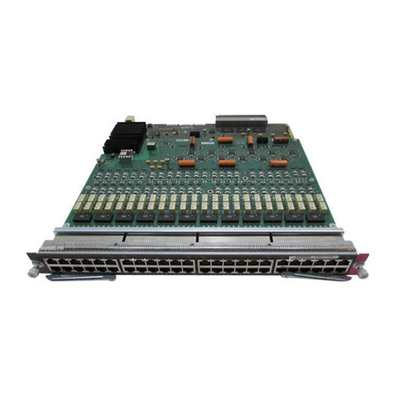
Catalyst 6500 Series Power over Ethernet
Daughter Cards Field-Upgrade Installation Note
This publication describes how to install and remove the following Catalyst 6500 series Power over
Ethernet (PoE) daughter cards. The PoE daughter cards and a brief description are listed in
Table 1
PoE Daughter Cards
PoE Daughter Card
WS-F6K-VPWR=
WS-F6K-VPWR-GE=
WS-F6K-GE48-AF=
WS-F6K-FE48X2-AF=
WS-F6K-48-AF=
Note
The WS-F6K-VPWR and WS-F6K-VPWR-GE PoE daughter cards are not interchangeable between
Ethernet modules.
Corporate Headquarters:
Cisco Systems, Inc., 170 West Tasman Drive, San Jose, CA 95134-1706 USA
Copyright © 2000–2005 Cisco Systems, Inc. All rights reserved.
Description
Catalyst 6500 series prestandard PoE daughter
card for 10/100 Ethernet modules.
Catalyst 6500 series prestandard PoE daughter
card for 10/100/1000 Ethernet modules.
Catalyst 6500 series IEEE 802.3af compliant PoE
daughter card for 10/100/1000 Ethernet modules.
Catalyst 6500 series IEEE 802.3af compliant PoE
daughter card.
Catalyst 6500 series IEEE 802.3af compliant PoE
daughter card for 10/100 and 10/100/1000
Ethernet modules.
Table
1.
Advertisement
Table of Contents

Related Manuals for Cisco WS-F6K-VPWR-GE


Summary of Contents for Cisco WS-F6K-VPWR-GE
- Page 1 Catalyst 6500 series IEEE 802.3af compliant PoE daughter card for 10/100 and 10/100/1000 Ethernet modules. Note The WS-F6K-VPWR and WS-F6K-VPWR-GE PoE daughter cards are not interchangeable between Ethernet modules. Corporate Headquarters: Cisco Systems, Inc., 170 West Tasman Drive, San Jose, CA 95134-1706 USA...
-
Page 2: Table Of Contents
• • Removing and Installing the WS-F6K-VPWR Inline-Power Daughter Card, page 15 • Removing and Installing the WS-F6K-VPWR-GE Inline-Power Daughter Card, page 19 • Removing and Installing the WS-F6K-GE48-AF Inline-Power Daughter Card, page 24 • Removing and Installing the WS-F6K-FE48X2-AF Inline-Power Daughter Card, page 29 •... -
Page 3: Overview
Maximum Power per Port PoE Daughter Card Supported on Ethernet Module (Watts) Port Speed WS-F6K-VPWR= WS-X6148-RJ-21 10/100 • WS-X6148-RJ-45 10/100 • WS-X6348-RJ-45 10/100 • WS-F6K-VPWR-GE= • WS-X6148-GE-TX 10/100/1000 • WS-X6548-GE-TX 10/100/1000 WS-F6K-GE48-AF= • WS-X6148-GE-TX 15.4 10/100/1000 • WS-X6548-GE-TX 15.4 10/100/1000... -
Page 4: Safety Overview
Safety Overview Only trained and qualified personnel should be allowed to install, replace, or service this equipment. Warning Statement 1030 Safety Overview Statement 1071—Warning Definition Warning IMPORTANT SAFETY INSTRUCTIONS This warning symbol means danger. You are in a situation that could cause bodily injury. Before you work on any equipment, be aware of the hazards involved with electrical circuitry and be familiar with standard practices for preventing accidents. - Page 5 Safety Overview Attention IMPORTANTES INFORMATIONS DE SÉCURITÉ Ce symbole d'avertissement indique un danger. Vous vous trouvez dans une situation pouvant entraîner des blessures ou des dommages corporels. Avant de travailler sur un équipement, soyez conscient des dangers liés aux circuits électriques et familiarisez-vous avec les procédures couramment utilisées pour éviter les accidents.
- Page 6 Safety Overview ¡Advertencia! INSTRUCCIONES IMPORTANTES DE SEGURIDAD Este símbolo de aviso indica peligro. Existe riesgo para su integridad física. Antes de manipular cualquier equipo, considere los riesgos de la corriente eléctrica y familiarícese con los procedimientos estándar de prevención de accidentes. Al final de cada advertencia encontrará el número que le ayudará...
- Page 7 Safety Overview Aviso INSTRUÇÕES IMPORTANTES DE SEGURANÇA Este símbolo de aviso significa perigo. Você se encontra em uma situação em que há risco de lesões corporais. Antes de trabalhar com qualquer equipamento, esteja ciente dos riscos que envolvem os circuitos elétricos e familiarize-se com as práticas padrão de prevenção de acidentes. Use o número da declaração fornecido ao final de cada aviso para localizar sua tradução nos avisos de segurança traduzidos que acompanham o dispositivo.
- Page 8 Safety Overview Catalyst 6500 Series Power over Ethernet Daughter Cards Field-Upgrade Installation Note 78-10826-08...
- Page 9 Safety Overview Hazardous voltage or energy is present on the backplane when the system is operating. Use caution Warning when servicing. Statement 1034 Catalyst 6500 Series Power over Ethernet Daughter Cards Field-Upgrade Installation Note 78-10826-08...
-
Page 10: Removing The Ethernet Switching Module
Removing the Ethernet Switching Module Removing the Ethernet Switching Module This section describes how to remove an Ethenet module from the switch chassis. Required Tools The following tools are required to perform the PoE daughter card removal and installation procedures: Number 2 Phillips screwdriver for the captive installation screws on the module on which the •... -
Page 11: Step 1
Removing the Ethernet Switching Module Caution To prevent ESD damage, handle switching modules by the carrier edges only. To remove the Ethernet switching module from the chassis, perform these steps: Disconnect any network interface cables attached to the module. Step 1 Verify that the captive installation screws on all of the other modules in the chassis are tight. - Page 12 Removing the Ethernet Switching Module Figure 1 Opening the Ejector Levers (Horizontal Chassis Shown) WS-X6624-FXS 24 PORT FXS ANALOG STATION WS-X6624-FXS 24 PORT FXS ANALOG STATION WS-X6624-FXS 24 PORT FXS ANALOG STATION WS-X6348-RJ-45 V 48 PORT 10/100 BASE-T ETHERNET SWITCHING MODULE INPUT OUTPU T...
- Page 13 Removing the Ethernet Switching Module Figure 2 Removing the Module from the Chassis (Horizontal Chassis Shown) WS-X6624-FXS 24 PORT FXS ANALOG STATION WS-X6624-FXS 24 PORT FXS ANALOG STATION WS-X6624-FXS 24 PORT FXS ANALOG STATION WS-X6348-RJ-45 V 48 PORT 10/100 BASE-T ETHERNET SWITCHING MODULE INPUT...
- Page 14 Inline-Power Daughter Card Removal and Installation Procedure Reference WS-F6K-VPWR= Removing and Installing the WS-F6K-VPWR Inline-Power Daughter Card, page 15 WS-F6K-VPWR-GE= Removing and Installing the WS-F6K-VPWR-GE Inline-Power Daughter Card, page 19 WS-F6K-GE48-AF= Removing and Installing the WS-F6K-GE48-AF Inline-Power Daughter Card, page 24 WS-F6K-FE48X2-AF=...
-
Page 15: Removing And Installing The Ws-F6K-Vpwr Inline-Power Daughter Card
WS-X6148-RJ-45 • WS-X6348-RJ-45 • The WS-F6K-VPWR inline-power daughter card supports Cisco prestandard inline power; it does not support IEEE 802.3af. Removing the WS-F6K-VPWR Inline-Power Daughter Card To remove the WS-F6K-VPWR inline-power daughter card from the module, perform these steps: Step 1... - Page 16 Removing and Installing the WS-F6K-VPWR Inline-Power Daughter Card Carefully remove the inline-power daughter card from the module (see Figure 4) and set the inline-power Step 3 daughter card on an antistatic mat or antistatic foam. Figure 4 Removing the Inline-Power Daughter Card (WS-F6K-VPWR) Inline-power module Baseboard...
- Page 17 Removing and Installing the WS-F6K-VPWR Inline-Power Daughter Card Installing the WS-F6K-VPWR Inline-Power Daughter Card To install the WS-F6K-VPWR inline-power daughter card on the Ethernet baseboard, perform these steps: Remove the inline-power daughter card from its protective packaging. Step 1 Position the inline-power daughter card over the module standoffs as shown in Figure Step 2 Figure 5...
- Page 18 Removing and Installing the WS-F6K-VPWR Inline-Power Daughter Card Carefully press down on the edges of the inline-power daughter card to seat the daughter card connectors Step 3 to the module connectors. Make sure that you firmly seat the inline-power daughter card connectors to the module Note connectors.
-
Page 19: Removing And Installing The Ws-F6K-Vpwr-Ge Inline-Power Daughter Card
Removing and Installing the WS-F6K-VPWR-GE Inline-Power Daughter Card Removing and Installing the WS-F6K-VPWR-GE Inline-Power Daughter Card The WS-F6K-VPWR-GE inline-power daughter card can be installed only on the following Ethernet modules: WS-X6148-GE-TX • WS-X6548-GE-TX • The WS-F6K-VPWR inline-power daughter card supports Cisco prestandard inline power; it does not support IEEE 802.3af. - Page 20 Removing and Installing the WS-F6K-VPWR-GE Inline-Power Daughter Card Grasp the inline-power daughter card at the front edges and carefully lift up to disconnect the Step 2 inline-power daughter card from the Ethernet module front connector. (See Figure Figure 8 Disconnecting the Inline-Power Daughter Card Front Connector (WS-F6K-VPWR-GE)
- Page 21 Carefully remove the inline-power daughter card from the Ethernet module and set it on an antistatic mat Step 4 or antistatic foam. Step 5 If you are installing a replacement WS-F6K-VPWR-GE inline-power daughter card, go to the “Installing the WS-F6K-VPWR-GE Inline-Power Daughter Card” section on page 21. If you are installing the Ethernet module back into the chassis, go to the “Installing the Ethernet Switching Module”...
- Page 22 Removing and Installing the WS-F6K-VPWR-GE Inline-Power Daughter Card Place your fingers on either side of the inline-power daughter card rear connector and press down to seat Step 2 the inline-power daughter card on the Ethernet module rear connector. (See Figure 11.)
- Page 23 Caution Do not overtighten the screws and the nuts because you might damage the inline-power daughter card. Figure 13 Attaching the Inline-Power Daughter Card to the Module (WS-F6K-VPWR-GE) Screw Step 5 You are now ready to install the Ethernet module back into the chassis. Go to the “Installing the Ethernet...
-
Page 24: Removing And Installing The Ws-F6K-Ge48-Af Inline-Power Daughter Card
The WS-F6K-GE48-AF inline-power daughter card can be installed only on the following Ethernet modules: WS-X6148-GE-TX • WS-X6548-GE-TX • The WS-F6K-GE48-AF inline-power daughter card supports both IEEE 802.3af and the Cisco Note prestandard. Removing the WS-F6K-GE48-AF Inline-Power Daughter Card To remove the WS-F6K-GE48-AF inline-power daughter card on the Ethernet module, perform these steps:... - Page 25 Removing and Installing the WS-F6K-GE48-AF Inline-Power Daughter Card Grasp the inline-power daughter card at the front edges and carefully lift up to disconnect the Step 2 inline-power daughter card from the Ethernet module front connector. (See Figure 15.) Figure 15 Disconnecting the Inline-Power Daughter Card Front Connector (WS-F6K-GE48-AF) Step 3 Grasp the inline-power daughter card near the back edges, as shown in...
- Page 26 Removing and Installing the WS-F6K-GE48-AF Inline-Power Daughter Card Carefully remove the inline-power daughter card from the Ethernet module and set it on an antistatic mat Step 4 or antistatic foam. Step 5 If you are installing a replacement WS-F6K-GE48-AF inline-power daughter card, go to the “Installing the WS-F6K-GE48-AF Inline-Power Daughter Card”...
- Page 27 Removing and Installing the WS-F6K-GE48-AF Inline-Power Daughter Card Place your fingers on either side of the inline-power daughter card rear connector near the standoffs and Step 2 press down to seat the inline-power daughter card on the module rear connector. (See Figure 18.) Figure 18...
- Page 28 Removing and Installing the WS-F6K-GE48-AF Inline-Power Daughter Card Attach the inline-power daughter card to the module with the twelve screws and the three nuts. (See Step 4 Figure 20.) Three screws that secure the daughter card to the module pass through openings in the daughter card heat sinks.
-
Page 29: Removing And Installing The Ws-F6K-Fe48X2-Af Inline-Power Daughter Card
Removing and Installing the WS-F6K-FE48X2-AF Inline-Power Daughter Card The WS-F6K-FE48X2-AF inline-power daughter card is supported only on the WS-X6148X2-RJ-45 Ethernet module. The WS-F6K-FE48X2-AF inline-power daughter card supports both IEEE 802.3af and the Cisco Note prestandard. Removing the WS-F6K-FE48X2-AF Inline-Power Daughter Card To remove the WS-F6K-FE48X2-AF inline-power daughter card on the module, perform these steps: Loosen and remove the 10 screws and the 2 nuts securing the inline-power daughter card to the module. - Page 30 Removing and Installing the WS-F6K-FE48X2-AF Inline-Power Daughter Card Grasp the inline-power daughter card at the rear edge and carefully lift up to disconnect the inline-power Step 2 daughter card from the module rear connector. (See Figure 22.) Figure 22 Disconnecting the Inline-Power Daughter Card Rear Connector (WS-F6K-FE48X2-AF) Rear connector location Grasp the inline-power daughter card near the front edges, as shown in...
- Page 31 Removing and Installing the WS-F6K-FE48X2-AF Inline-Power Daughter Card Carefully remove the inline-power daughter card from the module and set it on an antistatic mat or Step 4 antistatic foam. Step 5 If you are installing a replacement WS-F6K-FE48X2-AF inline-power daughter card, go to the “Installing the WS-F6K-FE48X2-AF Inline-Power Daughter Card”...
- Page 32 Removing and Installing the WS-F6K-FE48X2-AF Inline-Power Daughter Card Place your fingers on the stiffener bar and press down to seat the inline-power daughter card front Step 2 connector on the module. (See Figure 25.) Figure 25 Seating the Inline-Power Daughter Card Front Connector (WS-F6K-FE48X2-AF) Step 3 Position your fingers over the inline-power daughter card rear connector and press down firmly to seat the inline-power daughter card on the module rear connector.
- Page 33 Removing and Installing the WS-F6K-FE48X2-AF Inline-Power Daughter Card Attach the inline-power daughter card to the module with the 10 screws and the 2 nuts. (See Figure 27.) Step 4 Caution Do not overtighten the screws and the nuts because you might damage the inline-power daughter card. Figure 27 Securing the Inline-Power Daughter Card to the Module (WS-F6K-FE48X2-AF) Screw...
-
Page 34: Removing And Installing The Ws-F6K-48-Af Inline-Power Daughter Card
• WS-X6548-GE-TX • Note The WS-F6K-48-AF inline-power daughter card supports both IEEE 802.3af and the Cisco prestandard. Removing the WS-F6K-48-AF Inline-Power Daughter Card To remove the WS-F6K-48-AF inline-power daughter card on the Ethernet module, perform these steps: Step 1 Loosen and remove the 12 screws and the 3 nuts securing the inline-power daughter card to the module. - Page 35 Removing and Installing the WS-F6K-48-AF Inline-Power Daughter Card Grasp the inline-power daughter card at the front edges and carefully lift up to disconnect the Step 2 inline-power daughter card from the Ethernet module front connector. (See Figure 29.) Figure 29 Disconnecting the Inline-Power Daughter Card Front Connector (WS-F6K-48-AF) Step 3 Grasp the inline-power daughter card near the back edges, as shown in...
- Page 36 Removing and Installing the WS-F6K-48-AF Inline-Power Daughter Card Carefully remove the inline-power daughter card from the Ethernet module and set it on an antistatic mat Step 4 or antistatic foam. Step 5 If you are installing a replacement WS-F6K-48-AF inline-power daughter card, go to the “Installing the WS-F6K-48-AF Inline-Power Daughter Card”...
- Page 37 Removing and Installing the WS-F6K-48-AF Inline-Power Daughter Card Place your fingers on either side of the inline-power daughter card rear connector near the standoffs and Step 2 press down to seat the inline-power daughter card on the module rear connector. (See Figure 32.) Figure 32...
- Page 38 Removing and Installing the WS-F6K-48-AF Inline-Power Daughter Card Attach the inline-power daughter card to the module with the 12 screws and the 3 nuts. (See Figure 34.) Step 4 Caution Do not overtighten the screws and the nuts because you might damage the inline-power daughter card. Figure 34 Securing the Inline-Power Daughter Card to the Module (WS-F6K-48-AF) Screw...
-
Page 39: Installing The Ethernet Switching Module
Installing the Ethernet Switching Module Installing the Ethernet Switching Module Caution To prevent ESD damage, handle the modules by the carrier edges only. Caution During this procedure, wear grounding wrist straps to avoid ESD damage to the card. To reinstall the Ethernet switching module in the chassis, follow these steps: Verify that the captive installation screws are tightened on all modules installed in the switch chassis. - Page 40 Installing the Ethernet Switching Module Figure 35 Positioning the Module in a Horizontal Slot Chassis Insert module between slot guides EMI gasket WS-X6K-SUP2-2 GE Switch Load 100% CONSOLE PORT PORT 1 PORT 2 MODE CONSOLE SUPERVISOR2 PCMCIA EJECT WS-X6K-SUP2-2 GE Switch Load 100%...
- Page 41 Installing the Ethernet Switching Module Depending on the orientation of the slots in the chassis (horizontal or vertical), perform one of the Step 3 following two sets of steps: Horizontal slots Position the module in the slot. (See Figure 35.) Make sure that you align the sides of the module carrier with the slot guides on each side of the slot.
- Page 42 Installing the Ethernet Switching Module Figure 36 Clearing the EMI Gasket in a Horizontal Slot Chassis WS-X6K-SU P2-2GE Switch Load 100% CONSOLE PORT 1 PORT PORT 2 MODE CONSOLE SUPERVIS OR2 PCMCIA EJECT WS-X6K-SU P2-2GE Switch Load 100% CONSOLE PORT 1 PORT PORT 2 MODE...
- Page 43 Installing the Ethernet Switching Module Vertical slots Position the module in the slot. (See Figure 38.) Make sure that you align the sides of the module carrier with the slot guides on the top and bottom of the slot. Carefully slide the module into the slot until the EMI gasket along the right edge of the module makes contact with the module in the slot adjacent to it and both ejector levers have closed to approximately 45 degrees with respect to the module faceplate.
- Page 44 Installing the Ethernet Switching Module Figure 39 Clearing the EMI Gasket in a Vertical Slot Chassis Gap between the module EMI gasket and the module above it 1 mm STATUS Press left Press left INPUT OUTPUT FAIL INPUT OUTPUT FAIL Catalyst 6500 Series Power over Ethernet Daughter Cards Field-Upgrade Installation Note 78-10826-08...
- Page 45 Installing the Ethernet Switching Module Using the thumb and forefinger of each hand, grasp the two ejector levers and exert a slight pressure to the left, deflecting it approximately 0.040 inches (1 mm) creating a small gap between the module’s EMI gasket and the module adjacent to it. (See Figure 39.) Do not exert too much pressure on the ejector levers because they will bend and get damaged.
-
Page 46: Configuring The Module
Configuring the Module Configuring the Module Refer to the Catalyst 6500 Series Switch Software Configuration Guide or Catalyst 6500 Series Switch Cisco IOS Software Configuration Guide for information on configuring a Voice-over-IP (VoIP) network. Regulatory Standards Compliance When installed in a system, the Catalyst 6500 series switch modules comply with the standards listed in... -
Page 47: Translated Safety Warnings
Translated Safety Warnings Translated Safety Warnings This section repeats in multiple languages the basic warnings that appear in this publication. Statement 1001—Work During Lightning Activity Do not work on the system or connect or disconnect cables during periods of lightning activity. Warning Statement 1001 Waarschuwing... - Page 48 Translated Safety Warnings Statement 1021—SELV Circuit Warning To avoid electric shock, do not connect safety extra-low voltage (SELV) circuits to telephone-network voltage (TNV) circuits. LAN ports contain SELV circuits, and WAN ports contain TNV circuits. Some LAN and WAN ports both use RJ-45 connectors. Use caution when connecting cables.
- Page 49 Translated Safety Warnings ¡Advertencia! Para evitar la sacudida eléctrica, no conectar circuitos de seguridad de voltaje muy bajo (safety extra-low voltage = SELV) con circuitos de voltaje de red telefónica (telephone network voltage = TNV). Los puertos de redes de área local (local area network = LAN) contienen circuitos SELV, y los puertos de redes de área extendida (wide area network = WAN) contienen circuitos TNV.
- Page 50 Translated Safety Warnings Warnung Das Installieren, Ersetzen oder Bedienen dieser Ausrüstung sollte nur geschultem, qualifiziertem Personal gestattet werden. Avvertenza Questo apparato può essere installato, sostituito o mantenuto unicamente da un personale competente. Advarsel Bare opplært og kvalifisert personell skal foreta installasjoner, utskiftninger eller service på dette utstyret.
- Page 51 Translated Safety Warnings Statement 1034—Backplane Voltage Warning Hazardous voltage or energy is present on the backplane when the system is operating. Use caution when servicing. Statement 1034 Waarschuwing Er is gevaarlijke spanning of energie aanwezig op de achterplaat wanneer het systeem bediend wordt.
- Page 52 Translated Safety Warnings Aviso O sistema em funcionamento emite tensão ou energia elétrica perigosa no painel traseiro. Seja cauteloso ao fazer a manutenção. Advarsel Der er farlig spænding og energi på bagpladen når systemet er i brug. Vær forsigtig under servicering.
- Page 53 Translated Safety Warnings Statement 1041—Disconnecting Telephone-Network Cables Warning Before opening the unit, disconnect the telephone-network cables to avoid contact with telephone-network voltages. Statement 1041 Waarschuwing Voordat u de eenheid opent, dient u de verbinding met het telefoonnetwerk te verbreken door de kabels te ontkoppelen om zo contact met telefoonnetwerk-spanning te vermijden.
- Page 54 Translated Safety Warnings Statement 1072—Shock Hazard from Interconnections Warning Voltages that present a shock hazard may exist on Power over Ethernet (PoE) circuits if interconnections are made using uninsulated exposed metal contacts, conductors, or terminals. Avoid using such interconnection methods, unless the exposed metal parts are located within a restricted access location and users and service people who are authorized within the restricted access location are made aware of the hazard.
- Page 55 Translated Safety Warnings Advarsel I strømkretser med PoE (Power over Ethernet) kan det være spenninger som kan utgjøre støtfare hvis det blir foretatt sammenkoblinger med uisolerte, eksponerte kontakter, ledere eller terminaler av metall. Unngå å bruke slike sammenkoblingsmetoder med mindre de eksponerte metalldelene er i et område med begrenset tilgang, og brukere og servicepersonell som har tilgang til det begrensede området, blir gjort oppmerksom på...
-
Page 56: Obtaining Documentation
Obtaining Documentation Obtaining Documentation Cisco documentation and additional literature are available on Cisco.com. Cisco also provides several ways to obtain technical assistance and other technical resources. These sections explain how to obtain technical information from Cisco Systems. Cisco.com You can access the most current Cisco documentation at this URL: http://www.cisco.com/univercd/home/home.htm... -
Page 57: Documentation Feedback
Register to receive security information from Cisco. • A current list of security advisories and notices for Cisco products is available at this URL: http://www.cisco.com/go/psirt If you prefer to see advisories and notices as they are updated in real time, you can access a Product Security Incident Response Team Really Simple Syndication (PSIRT RSS) feed from this URL: http://www.cisco.com/en/US/products/products_psirt_rss_feed.html... -
Page 58: Obtaining Technical Assistance
Use the Cisco Product Identification (CPI) tool to locate your product serial number before submitting a web or phone request for service. You can access the CPI tool from the Cisco Technical Support Website by clicking the Tools & Resources link under Documentation & Tools. Choose Cisco Product Identification Tool from the Alphabetical Index drop-down list, or click the Cisco Product Identification Tool link under Alerts &... - Page 59 Cisco TAC engineer. The TAC Service Request Tool is located at this URL: http://www.cisco.com/techsupport/servicerequest For S1 or S2 service requests or if you do not have Internet access, contact the Cisco TAC by telephone. (S1 or S2 service requests are those in which your production network is down or severely degraded.) Cisco TAC engineers are assigned immediately to S1 and S2 service requests to help keep your business operations running smoothly.
-
Page 60: Obtaining Additional Publications And Information
CCSP, CCVP, the Cisco Square Bridge logo, Follow Me Browsing, and StackWise are trademarks of Cisco Systems, Inc.; Changing the Way We Work, Live, Play, and Learn, and iQuick Study are service marks of Cisco Systems, Inc.; and Access Registrar, Aironet, ASIST, BPX, Catalyst,...
Need help?
Do you have a question about the WS-F6K-VPWR-GE and is the answer not in the manual?
Questions and answers