Allen-Bradley 1734-VHSC5 User Manual
Very high-speed counter modules
Hide thumbs
Also See for 1734-VHSC5:
- Installation instructions manual (12 pages) ,
- User manual (64 pages) ,
- Installation instructions manual (30 pages)
Table of Contents
Advertisement
Advertisement
Table of Contents

Related Manuals for Allen-Bradley 1734-VHSC5


Summary of Contents for Allen-Bradley 1734-VHSC5
- Page 1 Very High-Speed Counter Modules 1734-VHSC5 and 1734-VHSC24 User Manual...
- Page 2 Important User Information Solid state equipment has operational characteristics differing from those of electromechanical equipment. Safety Guidelines for the Application, Installation and Maintenance of Solid State Controls (Publication SGI-1.1 available from your local Rockwell Automation sales office or online at http://literature.rockwellautomation.com) describes some important differences between solid state equipment and hard-wired electromechanical devices.
- Page 3 Summary of Changes Summary of Changes This publication contains new and revised information not in the last release. New and Revised Information See the table for a summary of the major changes in this manual. Chapter Change Preface Update of list of publications Indication that for specifications and safety approval information refer to the installation instructions Addition of Before You Begin section...
- Page 4 Summary of Changes Notes: Publication 1734-UM003B-EN-P - August 2005...
-
Page 5: Table Of Contents
Table of Contents Preface Preface Purpose of This Manual......P-1 Who Should Use This Manual ..... . P-1 Related Products and Documentation. - Page 6 Configuration Data ......3-4 Counter Configuration (Configuration Word 1) ..3-5 Filter Selection (Configuration Word 2 .
-
Page 7: Purpose Of This Manual
Preface Purpose of This Manual Read this manual for information about how to install, configure, and troubleshoot your module. For This Information About the Modules Chapter 1 Install the Modules Chapter 2 Input and Output Data Chapter 3 Configure Your Module Chapter 4 Access Instantiated Instances Chapter 5... -
Page 8: Related Products And Documentation
Preface Related Products and For specification, safety approval, and other information refer to the following. Documentation • Publication Number 1734-IN003 5V and 24V Very High-speed Counter Modules Installation Instructions For related 1734 products and documentation see the table. Description Cat. No. Publication Analog Input Modules 1734-IE2C... -
Page 9: Definitions
Preface Definitions The following define the intended operation of the module. Term Definition Lead Breakage Typically requires a shunt resistor (across the load) to detect 3 levels of current/input states - • Open (Wire Off, Device = ?) • Off (Wire OK, Device Off) •... - Page 10 Preface Operational Mode Zero Frequency Detection Input Monitored Counter None Encoder None Period/Rate Z Only Rate Measurement A Only Publication 1734-UM003B-EN-P - August 2005...
-
Page 11: What This Chapter Contains
Chapter About the Modules What This Chapter Contains Read this chapter to learn about types, features, and capabilities of the encoder/counter modules. Module Description and The modules install into the POINT I/O terminal base (1734-TB or 1734-TBS) and interface with the Point I/O DeviceNet Pass-through Features (1734-PDN) or the Point I/O DeviceNet Adapter (1734-ADN). -
Page 12: Operating Modes
About the Modules The outputs are rated to source 0.5A at 10 to 28.8V dc. The output may be tied to an input. This lets you cascade counters of multiple 1734-VHSC modules. The counter has 4 user-selectable On-Off values (windows) associated with it. Tie either output to any or all of the window signals. -
Page 13: Encoder Modes
About the Modules Channel A input is used as the counting pulse while channel B is used to determine the direction. [B = High, Count = Down; B = Low or floating (not connected), Count = Up] The Channel B input may be tied high or low for unidirectional counting, or toggled for bidirectional counting. - Page 14 About the Modules Absolute encoders typically have higher speed requirements (200 KHz typical) for motion control applications. An absolute encoder has a unique code associated with each position, so the exact position is always known, even if the system power is turned off. EXAMPLE Example of Multiplying Encoder Mode X1, X2 and X4 Input A...
-
Page 15: Period/Rate Mode
About the Modules X4 Multiplying Encoder Mode Quadrature input signals are used to count on leading and trailing edges of A and B for a bidirectional count, and channel B is used to determine the direction. [ B = leads A, Count = Down; B = follows A, Count = Up ] Period/Rate Mode The Period/Rate mode returns an incoming frequency and a total accumulated count to the POINTBus, by gating an internal 5 MHz... -
Page 16: Operation Of Scalar
About the Modules As the frequency of the incoming pulse train at the Z (Gate/Reset) terminal increases, the number of sampled pulses from the 5MHz clock decreases. Since accuracy is related to the number of pulses received over the sample period, the accuracy decreases with increasing frequencies at the Gate/Reset terminal. - Page 17 About the Modules Continuous/Rate Mode The Continuous/Rate Mode returns an incoming frequency and a total accumulated count to POINTBus, by gating an internal 5 MHz internal clock with an external signal. Similar to the Period/Rate mode except outputs in this mode are updated continuously.
-
Page 18: Rate Measurement Mode
About the Modules Rate Measurement Mode The Rate Measurement mode determines the frequency and total number of input pulses over a user-specified sample period. At the end of the interval, the module returns a value representing the sampled number of pulses and a value indicating the incoming frequency. -
Page 19: New Data Indicator
About the Modules New Data Indicator A two-bit counter, C1 and C0, is updated every time an event occurs, indicating that new data is available in the Stored/Accumulated Count words. Events are defined as: Any active gate transition in any of the Store Count (Counter or Encoder) modes The end of the gate sample period in either the Period / Rate, Continuous / Rate or PWM modes... -
Page 20: Operating Mode Features
1-10 About the Modules Operating Mode Features See the table for a summary of features active in each mode. Operating Feature Counter Encoder Period Continuous Rate Up / Down X1, X2 & X4 /Rate /Rate Measurement Preset Rollover Software Reset Store Count - Z Gate / Reset 4 modes... - Page 21 About the Modules 1-11 Store Count Mode 2: Store/Wait/Resume In mode 2, the rising edge of a pulse input on the Z Gate/Reset terminal reads and stores the current counter value in the Stored/Accumulated Count word and inhibit counting while the Z Gate/Reset terminal is high.
- Page 22 1-12 About the Modules Store-Reset/Start Start Counting Store Count, and Reset to zero Continue Counting Output Control To connect an output to a compare window, you could program the module accordingly: • Tie Output 0 to Window 0 • Program Window 0 ON Value to 2000 •...
-
Page 23: What This Chapter Contains
Chapter Install the Module What This Chapter Contains Read this chapter for information about how to install the modules. The 1734-VHSC module is a two-module set. Module 1 houses the 1734-VHSC functionality while module 2 provides screw terminals necessary to access chassis ground (Chas Gnd) and common (C). Module 2 also connects terminal 4 to 5 and terminal 6 to 7 for ease of wiring power to the input device. - Page 24 60529, as applicable, for explanations of the degrees of protection provided by different types of enclosure. Also, see the appropriate sections in this publication, as well as the Allen-Bradley publication 1770-4.1 (Industrial Automation Wiring and Grounding Guidelines), for additional installation requirements pertaining to this equipment.
-
Page 25: Install The Mounting Base Assembly
Install the Module Install the Mounting Base The wiring base assembly (1734-TB or 1734-TBS) consists of a mounting base (cat. no. 1734-MB) and a removable terminal block Assembly (cat. no. 1734-RTB or 1734-RTBS). You can install the assembly, or just the mounting base. To install the mounting base and wiring base assembly on the DIN rail, proceed as follows. -
Page 26: Install An I/O Module
Install the Module 3. Press firmly to seat the mounting base on the DIN rail. The mounting base snaps into place. 44013 Do not discard the end cap shipped with an adapter ATTENTION or communication interface. Use this end cap to cover the exposed interconnections on the last mounting base on the DIN rail. - Page 27 1734-VHSC24 - Position 2 1734-VHSC5 - Position 2 Turn the keyswitch to align the number with the notch.
-
Page 28: Install The Removable Terminal Block
Install the Module Install the Removable A removable terminal block comes with your mounting base assembly. Pull up on the RTB handle to remove and replace as Terminal Block necessary without removing any of the wiring. To reinsert the removable terminal block, use this procedure. 1. -
Page 29: Wire The Modules
Install the Module 2. Pull on the RTB handle to remove the removable terminal block. When you connect or disconnect the removable WARNING terminal block (RTB) with field-side power applied, an electrical arc can occur. This could cause an explosion in hazardous location installations. Be sure that power is removed or the area is nonhazardous before proceeding. - Page 30 Install the Module Module Status Network Status Status of Input A Status of Input B Status of Input Z Status of Output 0 Status of Output 1 Input A Input A Chassis Chassis Ground Ground Input B Input B RET 0 RET 1 Input Z Input Z...
-
Page 31: What This Chapter Contains
Very High-Speed Counter Module Input and Output Data What This Chapter Contains In this chapter, you learn about the input and output data table of your 1734-VHSC24 and 1734-VHSC5 Modules. For More Information About See Page Data Table Detailed Description of Data Table Information... -
Page 32: Detailed Description Of Data Table Information
Very High-Speed Counter Module Input and Output Data Scalar 8-bit value used to divide the Z input by 2 Output Ties 0 Output Ties 1 Rollover Value 32-bit value at which the counter is commanded to rollover Preset Value 32-bit value the counter is to be set to when CP is asserted On Value 1 32-bit value that sets the compare window Off Value 1... -
Page 33: Module/Channel Status And Programming Error Codes
Very High-Speed Counter Module Input and Output Data Finally, in rate measurement [7] configuration, it is the total number of pulses seen at the A input accumulated over each period as specified by the product of the time base x gate interval. The range of values occupy the entire 32-bit size from 0 ≤... - Page 34 Very High-Speed Counter Module Input and Output Data EEPROM Fault status bit (EF) - If a fault is detected with the EEPROM during power up tests, this bit is asserted to 1. It indicates that the content of the EEPROM has been corrupted, most likely caused by loss of power during an executing write.
- Page 35 Very High-Speed Counter Module Input and Output Data Output Data Counter Control (Word 1) Value Reset of stored/accumulated count. The transition of this bit from 0 to 1 clears the stored/accumulated count word. Counter Preset. The transition of this bit from 0 to 1 sets the counter to the value specified by the Preset words.
-
Page 36: Configuration Data
Very High-Speed Counter Module Input and Output Data Pulse Width Modulation (PWM) Value (Output Word 3) When the module is programmed for a PWM [3] configuration, the time base is enabled, the counter rollover, which is defined as the 1st ON and 1st OFF value for the respective channel is used. -
Page 37: Filter Selection
Very High-Speed Counter Module Input and Output Data Filter Selection (Configuration Word 2) This byte sets the A/B/Z input filters. Filter Selection No Filter 50 kHz (10 µs + 0 µs/-1.6 µs) 5 kHz (100 µs + 0 µs/-13.2 µs) 500 Hz (1.0 ms + 0 µs/-125 µs) 50 Hz (10 ms + 0 ms/-1.25 ms) A input not filtered... - Page 38 Very High-Speed Counter Module Input and Output Data In the counter modes (counter [0], x1 encoder [1], x2 encoder [2], pwm [3], x4 encoder [4]), it attenuates the counter display, for example, 20 divides count+1 by 20. The value may be in the range 0 < value ≤ 255. The result of requesting a number other than 1 performs the function: (COUNT + 1) / ATTENUATION.
-
Page 39: Scalar (Configuration Word 7)
Very High-Speed Counter Module Input and Output Data Scalar (Configuration Word 7) This byte scales the Z signal in the period/rate [5] and continuous/rate [6] configurations. If the filter is applied, then the filtered Z is scaled. Only one bit of the scalar should be set. Selecting a scalar causes accumulated counts to be adjusted accordingly. -
Page 40: Rollover (Configuration Word 8)
3-10 Very High-Speed Counter Module Input and Output Data Rollover (Configuration Word 10) This long word sets the number of counts the counter accumulates before rolling over. For example, a value of 1000 produces a count sequence of: 998, 999, 0, 1, 2… while incrementing or 2, 1, 0, 999, 998…... - Page 41 Very High-Speed Counter Module Input and Output Data 3-11 Safe State Values (Configuration Words 20 through 22) When either the host transitions to PROGRAM mode or a communication fault (broken network cable) occurs, the module copies these safe state words (counter control, output control, and PWM value) into its real-time working buffer.
- Page 42 3-12 Very High-Speed Counter Module Input and Output Data #108 (0x6c) Set/Get Counter Configuration Filter Selection Decimal Position Active Output Assembly Time Base or PWM Period Gate Interval Scalar Output 0 Ties Output 1 Ties Rollover Value Preset Value ON Value # 1 OFF Value #1 ON Value # 2 OFF Value #2...
-
Page 43: What This Chapter Contains
Chapter Configure Your Module What This Chapter Contains This chapter describes how to configure your Very High-Speed Counter modules with RSNetWorx. For More Information About See Page Configuration Overview Add the Adapter to Your Network Add I/O Modules to Your Network Set the Counter’s Parameters Check I/O Status and View the EDS File Configuration Overview... -
Page 44: Add I/O Modules To Your Network
Configure Your Module The scanner appears 1. Click here to expand the list on the network. of communication adapters. 2. Double-click here to choose the scanner. You can also click and drag the scanner name onto the network. Make sure you choose the 1734-ADN POINT I/O Scanner. - Page 45 Configure Your Module The out-of-the-box node setting for 1734 modules is 63. You can change the setting by using the node commissioning tool. The node commissioning tool is available either online or offline. If you commission a node online, you must power IMPORTANT down your system before the change takes place.
- Page 46 Configure Your Module 3. From the DeviceNet - RSNetWorx for DeviceNet dialog, complete the actions shown in the figure. 1. Go to the pulldown Tools. Select Node Commissioning. 2. Click Browse. 3. Select the module to change. 4. The node commissioning dialog returns.
-
Page 47: Set Counter Parameters
You see a counter module dialog with a series of tabs at the top of the dialog. See the tabs in the figure. These dialogs are for the 1734-VHSC24 module. Use identical dialogs for the 1734-VHSC5 module. These are the tabs you click to view the options. - Page 48 Configure Your Module 2. From the counter module dialog, complete the actions shown in the figure for the General dialog. The module’s name appears here. Type a description here. The module’s address appears here. (This field is read only.) This dialog also shows the At any point, you can click here to finish module’s device identity.
- Page 49 Configure Your Module 3. From the General dialog, click Device Parameters and complete the actions shown in the figure. This dialog appears after clicking the Device Parameters tab. If you want the existing parameters uploaded from the module, select Upload. The following dialog then shows the existing parameters set on the module.
- Page 50 Configure Your Module 4. To configure your module, from the Device Parameters dialog, select Configuration and complete the actions in the figure. To configure your module, select Configuration and modify the parameters as desired for your application. When complete, download to your module by clicking the Download to Device button.
-
Page 51: Check I/O Status And View/Edit The Eds File
Configure Your Module Check I/O Status and View Use this procedure to complete the entries on the dialogs you display by clicking the appropriate tab for I/O Defaults and EDS File. the EDS File 1. From the Counter Module screen, click I/O Defaults from the top of the dialog, completing the entries shown in the figure. - Page 52 4-10 Configure Your Module 2. From the Counter Module dialog, click EDS File from the top of the dialog, completing the entries shown in the figure. Click the EDS File tab to display the statistics of the EDS file used to configure this module.
-
Page 53: What This Chapter Contains
Chapter Access Instantiated Instances What This Chapter Contains In this chapter, you learn how to access imbedded Instantiated Instances (assemblies) in the software. The Very High-Speed Counter Module uses several words to communicate real time input and output data as well as non-real time module information (such as description and revision) and configuration. - Page 54 Access Instantiated Instances 2. From the Service Class Instance Attribute Editor Warning dialog, click Yes. You see the Service Class Instance Attribute Editor dialog. 3. From the Service Class Instance Attribute Editor dialog, complete these actions, referring to the figure. a.
-
Page 55: Assemblies
Access Instantiated Instances See the figure for an example, where you select Instance 101 (polled connection). 1. Type in the instance number here. This is an example of assembly number 102 (0x66). The class is always 4 and the attribute is always 3. 2. - Page 56 Access Instantiated Instances Instances Services Field Bytes #101 (0x65) Present Channel Data Status #102 (0x66) Stored Channel Data Status #103 (0x67) Present Channel Data Stored Channel Data Status #104 (0x68) Programming Error Code #105 (0x69) Set/Get Counter Control Output Control #106 (0x6a) Set/Get PWM Value...
-
Page 57: Use The Indicators For Troubleshooting
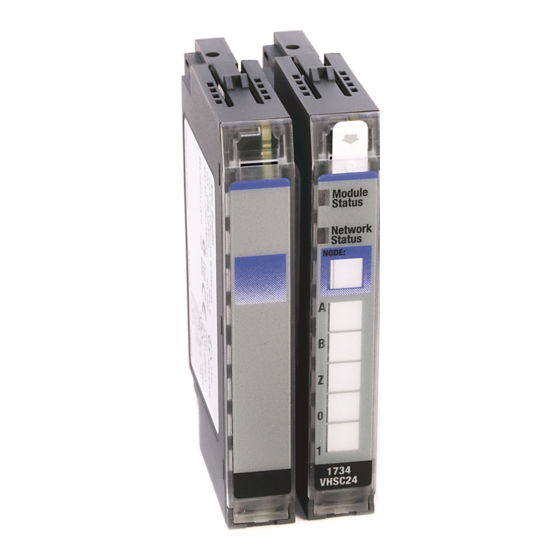
Chapter Troubleshoot with the Indicators Use the Indicators for Each 1734-VHSC module has 7 indicators on the frontplate. Use these indicators for troubleshooting, referring to the figures and tables. Troubleshooting Module Status Network Status Status of Input A Status of Input B Status of Input Z Status of Output 0 Status of Output 1... - Page 58 Troubleshoot with the Indicators Indication Probable Cause Network Status Device is not online. - Device has not completed dup_MAC_id test. - Device not powered - check module status indicator. Flashing Green Device is online but has no connections in the established state.
-
Page 59: What This Appendix Contains
Appendix Configure Modules in RSLogix 5000 Software What This Appendix Read this appendix for information about how to configure your modules in RSLogix 5000 software, including how to complete entries Contains on these dialogs. • Fault/Program Action • Counter Configuration •... - Page 60 Configure Modules in RSLogix 5000 Software When you change Connection and Data Format note the following. • You do not delete the existing module. • You do not create a new module. • You bring forward all possible configuration data for the new setting.
-
Page 61: Configure Your Module
Configure Modules in RSLogix 5000 Software Configure Your Module To configure your module in RSLogix 5000, use this procedure. 1. Configure your adapter, referring to the user manual for your adapter for information on how to configure the adapter and add modules to the I/O configuration to include selecting a controller and communication module. -
Page 62: Work With The Fault/Program Action Dialog
Configure Modules in RSLogix 5000 Software Work with the Use these procedures to complete the entries from this dialog, which is not available with a Listen Only connection. Fault/Program Action Dialog 1. Check the checkboxes, as shown in the table. Check this Checkbox Counter Reset... - Page 63 Configure Modules in RSLogix 5000 Software 3. For the appropriate Output number, check the checkboxes for the values in the table. Value Description Force Output If checked, you turn outputs on if you check Output Enable. If unchecked, you control the outputs by a compare match or as directed by the PWM settings.
-
Page 64: Work With The Counter Configuration Dialog
Configure Modules in RSLogix 5000 Software Work with the Counter In Hard Run mode, you disable all controls on the Counter Configuration dialog, in addition to the enable and disable state for Configuration Dialog each control. Use the following procedures to complete entries from this dialog. After you select Type, refer to the table to see what other entries are available in the dialog. - Page 65 Configure Modules in RSLogix 5000 Software 1. For Type, select one of these to set the Counter Configuration mode. • Counter (default) • Encoder X1, Encoder X2, or Encoder X4 • Pulse Width Modulation (PWM) • Period/Rate • Continuous Rate •...
- Page 66 Configure Modules in RSLogix 5000 Software 9. For Time Base, select a value between 10 and 3000 milliseconds, in multiples of 10, referring to the table. Selections for Period/Rate and Rate Measurement For This Value Default Is: Select Frequency Precision X 0.0001 X 0.001 X 0.01...
- Page 67 Configure Modules in RSLogix 5000 Software 14. For Scalar, choose one of these. • 1 • 2 • 4 • 8 • 16 • 32 • 64 • 128 When the value for Scalar is one of the following, note that frequency precision <...
-
Page 68: Work With The Output Configuration Dialog
A-10 Configure Modules in RSLogix 5000 Software Work with the Output Use this dialog to make On Value and Off Value entries for each output you select. If you make no entries for Outputs on this dialog, Configuration Dialog leave On Value and Off Value entries as 0; otherwise, use these procedures. - Page 69 Index 1-10 active features per mode indicators 3-8, 3-11 assembly selection input status indicator input voltage range input word - present channel data installation base assembly, mounting module removable terminal block wiring base assembly checking I/O defaults class instance attribute editor class instance editor commissioning a node keyswitch position...
- Page 70 Index scalar selection selecting a filter parameter setting selecting counter type period rate mode - operation selecting the scalar setting period/rate mode setting module parameters positioning the keyswitch 3-10 setting rollover counts present channel data 3-11 setting safe state values 3-10 preset configuration 3-10...
- Page 71 ___No, there is no need to contact me ___Yes, please call me ___Yes, please email me at _______________________ ___Yes, please contact me via _____________________ Return this form to: Rockwell Automation Technical Communications, 1 Allen-Bradley Dr., Mayfield Hts., OH 44124-9705 Fax: 440-646-3525 Email: RADocumentComments@ra.rockwell.com Publication CIG-CO521C-EN-P- May 2003...
- Page 72 PLEASE FASTEN HERE (DO NOT STAPLE) Other Comments PLEASE FOLD HERE NO POSTAGE NECESSARY IF MAILED IN THE UNITED STATES BUSINESS REPLY MAIL FIRST-CLASS MAIL PERMIT NO. 18235 CLEVELAND OH POSTAGE WILL BE PAID BY THE ADDRESSEE...
- Page 74 Back Cover Publication 1734-UM003B-EN-P - August 2005 PN 957974-42 Supersedes Publication 1734-UM003A-EN-P- August 2000 © 2005 Rockwell International Corporation. Printed in the U.S.A.
Need help?
Do you have a question about the 1734-VHSC5 and is the answer not in the manual?
Questions and answers