
Related Manuals for Allen-Bradley 1734-IE4S


Summarization of Contents
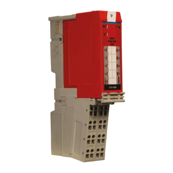
Point Guard I/O Safety Modules
User Manual
Indicates this document is a user manual for the modules.
Original Instructions
Signifies this document contains original instructions for the product.
Important User Information
General Safety Precautions
Essential safety guidelines for installation, operation, and maintenance of the equipment.
Specific Safety Warnings
Details on WARNING, ATTENTION, and IMPORTANT notes for user safety and product understanding.
Electrical Hazard Warnings
Specific warnings related to SHOCK HAZARD, BURN HAZARD, and ARC FLASH HAZARD.
Chapter 1 POINT Guard I/O Overview
Understand Suitability for Use
Guidance on determining product suitability for specific applications and system requirements.
Safety Precautions
Essential precautions for proper use of POINT Guard I/O modules, including installation and replacement.
POINT Guard I/O Modules in CIP Safety Systems
How POINT Guard I/O modules integrate into CIP Safety networks using EtherNet/IP and DeviceNet.
Safety Application Requirements
Core requirements for utilizing POINT Guard I/O in safety applications up to Performance Level e and SIL CL3.
Chapter 2 Safety Inputs, Safety Outputs, and Safety Data
Safe States
Defines the safe states for digital and analog POINT Guard I/O modules, typically the OFF state.
Safety Inputs (1734-IB8S)
Details on how safety inputs are used to monitor safety input devices and the use of test outputs.
Dual-channel Mode and Discrepancy Time
Explains dual-channel operation, discrepancy evaluation, and fault detection for safety inputs.
Safety Analog Inputs (1734-IE4S)
Configuration options for analog input channels, including ranges, scaling, and filtering.
Safety Outputs (1734-OB8S and 1734-OBV2S)
Information on safety output configurations, including test pulses and dual-channel modes.
Muting Lamp Operation (1734-IB8S)
How muting status bits operate and are monitored for test outputs T1 and T3.
Chapter 3 Guidelines for Placing Power Supplies and Modules in a System
Choosing a Power Supply
Guidance on selecting appropriate power supplies for POINTBus backplane and field power.
Placing Series A Digital and Analog Modules
Installation and thermal derating guidelines for Series A POINT Guard I/O modules.
Placing Series B Digital Modules
Installation guidelines for Series B POINT Guard I/O modules, considering ambient temperature limits.
Chapter 4 Install the Module
Precautions
General precautions for using and installing modules, including temperature limits and electrical safety.
European Hazardous Location Approval
Details on European hazardous location certifications, protection types, and special conditions for safe use.
North American Hazardous Location Approval
Information on products suitable for Class I, Division 2 hazardous locations in North America.
Environment and Enclosure
Requirements for mounting equipment within suitable enclosures for specific environmental conditions.
Install the Mounting Base
Steps for installing the mounting base assembly and ensuring proper seating on the DIN rail.
Wire Modules
Guidelines for correctly wiring modules, including routing, cable types, and connections.
Terminal Layout
Diagrams showing the field wiring connections for various POINT Guard I/O modules.
Wiring Examples
Practical examples of wiring configurations for different safety devices and applications.
Chapter 5 Configure the Module in a GuardLogix Controller System
Set up the Module
Initial steps for setting up POINT Guard I/O modules within a GuardLogix controller using Logix Designer.
Add and Configure the Ethernet Bridge
Procedure for adding and configuring the Ethernet bridge module in the I/O configuration tree.
Add and Configure Safety Digital Input Modules
Steps to add and configure safety digital input modules, including general properties and input settings.
Configure the Safety Digital Inputs
Detailed steps for configuring safety digital input parameters like operation type, mode, and delays.
Add and Configure Safety Digital Output Modules
Process for adding and configuring safety digital output modules, including general properties and output settings.
Configure the Safety Digital Outputs
Steps to configure safety digital output parameters such as point mode, operation type, and error latch time.
Add and Configure Safety Analog Input Modules
Procedure for adding and configuring safety analog input modules, including general properties and input configurations.
Configure the Safety Analog Input Channel Operation
Configuring analog input channels for operation type, discrepancy settings, deadbands, and offsets.
Configure the Safety Analog Inputs
Setting up analog input parameters like point mode, input range, filter, and engineering scaling values.
Configure Tachometer Operation
Steps to configure module operation in tachometer mode, including dual low detection and trigger settings.
Configure Safety Connections
Establishing safety connections between the controller and POINT Guard I/O modules, including RPI settings.
Chapter 6 Configure the Module for a SmartGuard Controller
Before You Begin
Lists required software and hardware items for configuring a SmartGuard controller and POINT Guard I/O modules.
Set the Node Address
Procedure for setting the node address of POINT Guard I/O modules using RSNetWorx for DeviceNet software.
Auto-addressing with a 1734-PDN Adapter
Utilizing the auto-address feature with a 1734-PDN adapter for sequential module addressing.
Set Up Your DeviceNet Network
Steps to set up the DeviceNet network using RSLinx and RSNetWorx for DeviceNet software.
Configure the POINT Guard I/O Modules
Configuring POINT Guard I/O modules, including digital safety inputs, test outputs, and digital safety outputs.
Configure the SmartGuard Controller
Setting up input and output connections and completing the controller configuration.
Save and Download Module Configuration
Recommends saving and downloading the module configuration after setup.
Chapter 7 Configuring Safety Connections between a GuardLogix Controller and POINT Guard I/O Modules on a DeviceNet Network
Configure the Module in RSNetWorx for DeviceNet Software
Tasks required in RSNetWorx for DeviceNet software before adding modules to a GuardLogix project.
Add the POINT Guard I/O Module to the Controller Project
Steps to add the POINT Guard I/O module to the controller project using the Logix Designer application.
Complete the Safety Configuration
Copying configuration signatures and safety network numbers from RSNetWorx to Logix Designer.
Download the DeviceNet Network Configuration
Procedure for downloading the DeviceNet network configuration after setting it up.
Verify Your DeviceNet Safety Configuration
Running the Safety Device Verification Wizard to confirm safety device configuration and functionality.
Select Devices to Verify
Choosing devices for verification using checkboxes in the Verify Safety Device Configuration dialog box.
Lock Safety Devices
Performing verification steps and locking safety device configurations to ensure security.
Chapter 8 Replacing POINT Guard I/O Modules
The Safety Network Number
Explanation of the Safety Network Number (SNN) and its importance in safety network identification.
Manually Setting the Safety Network Number
Procedures for manually setting the Safety Network Number (SNN) for safety connection integrity.
Resetting a Module to Out-of-box Condition
Steps to reset a POINT Guard I/O module to its factory default configuration.
Replace a Module in a GuardLogix System on an EtherNet/IP Network
Replacing modules in a GuardLogix system on an EtherNet/IP network, including configuration options.
Replace a Module When Using a SmartGuard or GuardLogix Controller on a DeviceNet Network
Steps for replacing I/O modules on a DeviceNet network with SmartGuard or GuardLogix controllers.
Need help?
Do you have a question about the 1734-IE4S and is the answer not in the manual?
Questions and answers