Table of Contents
Advertisement
Installation Instructions
POINT I/O RTD and Isolated
Thermocouple Input Modules
Catalog Numbers 1734-IR2, 1734-IR2K, 1734-IR2E, 1734-IT2I,
1734-IT2IK, Series C
Catalog numbers with the suffix 'K' are conformal coated and their specifications are the
same as non-conformal coated catalogs.
Table of Contents
Topic
Page
2
3
3
4
5
7
9
10
12
14
15
17
18
20
Advertisement
Table of Contents

Related Manuals for Allen-Bradley 1734-IR2


Summary of Contents for Allen-Bradley 1734-IR2
-
Page 1: Table Of Contents
Installation Instructions POINT I/O RTD and Isolated Thermocouple Input Modules Catalog Numbers 1734-IR2, 1734-IR2K, 1734-IR2E, 1734-IT2I, 1734-IT2IK, Series C Catalog numbers with the suffix ‘K’ are conformal coated and their specifications are the same as non-conformal coated catalogs. Table of Contents Topic Page Important User Information... -
Page 2: Important User Information
2 POINT I/O RTD and Isolated Thermocouple Input Modules Important User Information Solid-state equipment has operational characteristics differing from those of electromechanical equipment. Safety Guidelines for the Application, Installation, and Maintenance of Solid-State Controls (Publication SGI-1.1 available from your local Rockwell Automation Sales Office or online at http://www.rockwellautomation.com/literature/) describes some important differences between solid-state equipment and hard-wired electromechanical devices. -
Page 3: Environment And Enclosure
POINT I/O RTD and Isolated Thermocouple Input Modules Environment and Enclosure ATTENTION: This equipment is intended for use in a Pollution Degree 2 industrial environment, in overvoltage Category II applications (as defined in EN/IEC 60664-1), at altitudes up to 2000 m (6562 ft) without derating. This equipment is not intended for use in residential environments and may not provide adequate protection to radio communication services in such environments. -
Page 4: North American Hazardous Location Approval
4 POINT I/O RTD and Isolated Thermocouple Input Modules North American Hazardous Location Approval The following information applies when Informations sur l’utilisation de cet équipement operating this equipment in hazardous en environnements dangereux: locations: Products marked "CL I, DIV 2, GP A, B, C, D" are suitable Les produits marqués "CL I, DIV 2, GP A, B, C, D"... -
Page 5: European Hazardous Location Approval
POINT I/O RTD and Isolated Thermocouple Input Modules European Hazardous Location Approval The following applies to products marked II 3 G: • Are intended for use in potentially explosive atmospheres as defined by European Union Directive 2014/34/EU and has been found to comply with the Essential Health and Safety Requirements relating to the design and construction of Category 3 equipment intended for use in Zone 2 potentially explosive atmospheres, given in Annex II to this Directive. - Page 6 6 POINT I/O RTD and Isolated Thermocouple Input Modules ATTENTION: If this equipment is used in a manner not specified by the manufacturer, the protection provided by the equipment may be impaired. ATTENTION: Read this document and the documents listed in the Additional Resources section about installation, configuration, and operation of this equipment before you install, configure, operate, or maintain this product.
-
Page 7: Before You Begin
POINT I/O RTD and Isolated Thermocouple Input Modules Before You Begin Note that this series C product can be used with the following: • DeviceNet® and PROFIBUS adapters • ControlNet® and EtherNet/IP™ adapters, using RSLogix 5000® software, version 11 or later See the figures to familiarize yourself with major parts of the module, noting that the wiring base assembly is one of the following: •... - Page 8 8 POINT I/O RTD and Isolated Thermocouple Input Modules Description Description Module locking mechanism 1734-TB or 1734-TBS mounting base Slide-in writable label Interlocking side pieces Insertable I/O module Mechanical keying (orange) Removable terminal block (RTB) handle DIN rail locking screw (orange) Removable terminal block with screw Module wiring diagram (1734-RTB) or spring clamp (1734-RTBS)
-
Page 9: Install The Mounting Base
POINT I/O RTD and Isolated Thermocouple Input Modules Install the Mounting Base To install the mounting base on the DIN rail (Allen-Bradley® part number 199-DR1; 46277-3; EN50022), proceed as follows. ATTENTION: This product is grounded through the DIN rail to chassis ground. -
Page 10: Install The Module
10 POINT I/O RTD and Isolated Thermocouple Input Modules Slide the mounting base down to make the interlocking side pieces engage the adjacent module or adapter. Press firmly to seat the mounting base on the DIN rail. The mounting base snaps into place. Be sure that the orange DIN rail locking screw is in the horizontal position and that it has engaged the DIN rail. - Page 11 POINT I/O RTD and Isolated Thermocouple Input Modules 1734-TB Base 1734-TOP Base Be sure the DIN-rail locking screw is in the Turn the keyswitch to horizontal position. align the number with the notch. Notch Turn the keyswitch to position 3 is shown. align the number with the notch.
-
Page 12: Install The Removable Terminal Block
12 POINT I/O RTD and Isolated Thermocouple Input Modules Install the Removable Terminal Block A Removable Terminal Block (RTB) is supplied with your wiring base assembly. To remove, pull up on the RTB handle. This allows the mounting base to be removed and replaced as necessary without removing any of the wiring. - Page 13 POINT I/O RTD and Isolated Thermocouple Input Modules WARNING: For 1734-RTBS and 1734-RTB3S, to latch and unlatch the wire, insert a bladed screwdriver (catalog number 1492-N90 – 3 mm diameter blade) into the opening at approximately 73° (blade surface is parallel with top surface of the opening) and push up gently.
-
Page 14: Remove A Mounting Base
14 POINT I/O RTD and Isolated Thermocouple Input Modules Remove a Mounting Base To remove a mounting base, you must remove any installed module and the module installed in the base to the right. Remove the removable terminal block, if wired. WARNING: When you insert or remove the module while backplane power is on, an electrical arc can occur. -
Page 15: Wire The Module
POINT I/O RTD and Isolated Thermocouple Input Modules Wire the Module WARNING: If you connect or disconnect wiring while the field-side power is on, an electrical arc can occur. This could cause an explosion in hazardous location installations. Be sure that power is removed or the area is nonhazardous before proceeding. - Page 16 16 POINT I/O RTD and Isolated Thermocouple Input Modules POINT I/O RTD Input Module Wiring – 1734-IR2, 1734-IR2K, 1734-IR2E Channel High Signal (+) Low Signal (-) Return Shield In 0/A In 0/B In 1/A In 1/B For improved 1734-RTB calibration wiring diagrams, refer to the POINT I/O™ RTD and Isolated Thermocouple Input Modules Release Notes, publication, 1734-RN005.
-
Page 17: Communicate With The Module
POINT I/O RTD and Isolated Thermocouple Input Modules Communicate with the Module POINT I/O modules send (produce) and receive (consume) I/O data (messages). You map this data onto the processor’s memory. The 1734-IR2, 1734-IR2K, and 1734-IR2E modules produce 6 bytes of input data (scanner Rx) and fault status data. -
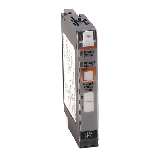
Page 18: Interpret Status Indicators
18 POINT I/O RTD and Isolated Thermocouple Input Modules Interpret Status Indicators Refer to the following diagram and table for information on how to interpret the status indicators. POINT I/O RTD and Isolated Thermocouple Input Modules 1734-IR2, 1734-IR2K, 1734-IT2I, 1734-IT2IK 1734-IR2E Module Module status... - Page 19 POINT I/O RTD and Isolated Thermocouple Input Modules Indicator Status for Modules Status Description Network status Off Device is not online: - Device has not completed dup_MAC-id test. - Device not powered – check module status indicator. Flashing green Device is online but has no connections in the established state. Green Device is online and has connections in the established state.
-
Page 20: Specifications
20 POINT I/O RTD and Isolated Thermocouple Input Modules Specifications POINT I/O RTD Input Modules – 1734-IR2, 1734-IR2K, 1734-IR2E Attribute 1734-IR2, 1734-IR2K 1734-IR2E Number of inputs 2 single-ended, non-isolated Resolution 16 bits 16 bits 9.5 mΩ/cnt 2.4 mΩ/cnt 0.03 °C/cnt (Pt385 @ 25 °C) 0.006 °C/cnt (Pt385 @ 25 °C) [0.05 °F/cnt (Pt385 @ 77 °F)] [0.0114 °F/cnt (Pt385 @ 77 °F)]... - Page 21 POINT I/O RTD and Isolated Thermocouple Input Modules POINT I/O RTD Input Modules – 1734-IR2, 1734-IR2K, 1734-IR2E Attribute 1734-IR2, 1734-IR2K 1734-IR2E Common mode rejection ratio 120 dB Normal mode rejection ratio 100 dB Notch filter -3 dB settable at the following: 13.1 Hz @ Notch = 50 Hz 15.7 Hz @ Notch = 60 Hz 26.2 Hz @ Notch = 100 Hz...
- Page 22 22 POINT I/O RTD and Isolated Thermocouple Input Modules POINT I/O Isolated Thermocouple Input Module – 1734-IT2I, 1734-IT2IK Attribute Value Input voltage ±75 mV Absolute accuracy 0.1% Full Scale @ 25 °C (77 °F) Accuracy drift with temp. 30 ppm/°C Input impedance 100 KΩ...
- Page 23 POINT I/O RTD and Isolated Thermocouple Input Modules General Specifications Attribute Value Terminal base 1734-TBCJC wiring base assembly – 1734-IT2I, 1734-IT2IK 1734-TB, 1734-TBS, 1734-TOP, or 1734-TOPS wiring base assembly – 1734-IR2, 1734-IR2K, 1734-IR2E Terminal base screw torque 0.8 Nm (7 lb-in.) Indicators, logic side 1 green/red –...
- Page 24 24 POINT I/O RTD and Isolated Thermocouple Input Modules Environmental Specifications Attribute Value Temperature, operating IEC 60068-2-1 (Test Ad, Operating Cold), IEC 60068-2-2 (Test Bd, Operating Dry Heat), IEC 60068-2-14 (Test Nb, Operating Thermal Shock): -20…55 °C (-4…131 °F) Temperature, surrounding air, 55 °C (131 °F) max.
- Page 25 POINT I/O RTD and Isolated Thermocouple Input Modules Certifications Certification (when Value product is marked) c-UL-us UL Listed Industrial Control Equipment, certified for US and Canada. See UL File E65584. UL Listed for Class I, Division 2 Group A,B,C,D Hazardous Locations, certified for U.S.
- Page 26 Rockwell Automation maintains current product environmental information on its website at http://www.rockwellautomation.com/rockwellautomation/about-us/sustainability-ethics/product-environmental-compliance.page. Allen-Bradley, POINT I/O, Rockwell Automation, Rockwell Software, RSLogix 5000, and TechConnect are trademarks of Rockwell Automation, Inc. ControlNet, DeviceNet, and EtherNet/IP are trademarks of ODVA, Inc. Trademarks not belonging to Rockwell Automation are property of their respective companies.
Need help?
Do you have a question about the 1734-IR2 and is the answer not in the manual?
Questions and answers