
Related Manuals for Sega WaveRunner GP


Summary of Contents for Sega WaveRunner GP
- Page 1 1ST PRINTING JUNE ‘03 www.seuservice.com STD Version Owner’s Manual SEGA ENTERPRISES, INC. USA MANUAL NO. 999-1869 Game Code: WRG...
- Page 2 VISIT OUR WEBSITE!
- Page 3 BEFORE USING THE PRODUCT, BE SURE TO READ THE FOLLOWING: To maintain the safety: To ensure the safe usage of the product, be sure to read the following before using the product. The following instructions are intended for the users, operators and the personnel in charge of the opera- tion of the product.
- Page 4 SEGA shall not be held responsible for any accidents, compensation for damage to a third party, resulting from the specifications not designated by SEGA.
-
Page 5: Table Of Contents
TABLE OF CONTENTS BEFORE USING THE PRODUCT, BE SURE TO READ THE FOLLOWING: TABLE OF CONTENTS INTRODUCTION OF THE OWNER’S MANUAL 1. HANDLING PRECAUTIONS ..................1 - 2 2. PRECAUTIONS CONCERNING INSTALLATION LOCATION ........3 - 4 3. OPERATION ........................5 - 7 4. -
Page 6: Introduction Of The Owners Manual
WAVERUNNER GP STANDARD VERSION. This manual is intended for the owners, personnel and managers in charge of operation of the product. Operate the product after carefully reading and sufficiently understand- ing the instructions. - Page 7 DEFINITION OF LOCATION MAINTENANCE MAN AND SERVICEMAN Non-technical personnel who do not have technical knowledge and expertise should refrain from performing such work that this manual requires the location's main- tenance man or a serviceman to carry out, or work which is not explained in this WARNING! manual.
- Page 8 NOTES:...
-
Page 9: Handling Precautions
• SEGA shall not be held responsible for damage, compensation for damage to a third party, caused by specification changes not designated by SEGA. - Page 10 Some parts are the ones designed and manufactured not specifically for this game machine. The manufacturers may discontinue, or change the specifications of, such general-purpose parts. If this is the case, Sega cannot repair or replace a failed game machine whether or not a warranty period has expired.
-
Page 11: Precautions Concerning Installation Location
2. PRECAUTIONS CONCERNING INSTALLATION LOCATION This product is an indoor game machine. Do not install it outside. Even indoors, avoid installing in places mentioned below so as not to cause a fire, electric shock, injury and or malfunctioning. WARNING! Places subject to rain or water leakage, or places subject to high humidity in the proximity of an indoor swimming pool and or shower, etc. - Page 12 To avoid machine malfunctioning and a fire, do not place any obstacles near the ventilation opening. SEGA shall not be held responsible for damage, compensation for damage to a third party, resulting from the failure to observe this instruction.
-
Page 13: Operation
3. OPERATION PRECAUTIONS TO BE HEEDED BEFORE STARTING THE OPERATION To avoid injury and trouble, be sure to constantly give careful attention to the behavior and manner of the visitors and players. In order to avoid accidents, check the following before starting the operation: To ensure maximum safety for the players and the customers, ensure that where the product is operated has sufficient lighting to allow any warnings to be read. - Page 14 Do not put any heavy item on this product. Placing any heavy item on the product can cause a falling down accident or parts damage. WARNING! Do not climb on the product. Climbing on the product can cause falling down ac- cidents.
- Page 15 PRECAUTIONS TO BE HEEDED DURING OPERATION (PAYING ATTENTION TO CUSTOMERS) To avoid injury and trouble, be sure to constantly give careful attention to the behavior and manner of the visitors and players. To avoid injury and accidents, those who fall under the following categories are not allowed to play the game.
-
Page 16: Name Of Parts
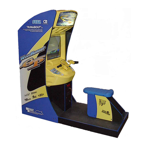
4. NAME OF PARTS Marquee Monitor Control Panel Seat TABLE 4 Dimensions and Weights Items Width X Depth X Height Weight Cabinet 30.25in (W) X 35.75in (D) X 77.5in (H) 450 lbs Seat Section 30.25in (W) X40.75in (D) X 25.25in (H) 100 lbs When assembled 30.25in (W) X 76.5in (D) X 77.5in (H) -
Page 17: Accessories
5. ACCESSORIES When transporting the machine, make sure that the following parts are supplied. TABLE 5 a ACCESSORIES DESCRIPTION OWNERS MANUAL KEY MASTER Part No. (Qty.) 220-5576 (2) 999-XXXX (1) Note For opening/closing the doors Figures KEY (2) If Part No. has no description, the Number has not been For the CASHBOX DOOR registered or can not be registered. - Page 18 HOW TO USE THE CARTON BOX When requesting for the replacement/repair of this product's Game Board (NAOMI STOP BOARD), follow the instructions below. Transporting the Game Board in an undesig- nated status is unacceptable. An erroneous handling can cause parts damage. IMPORTANT! •...
-
Page 19: Assembling And Installation
6. ASSEMBLING AND INSTALLATION Perform assembly work by following the procedure herein stated. Failing to com- ply with the instructions can cause electric shock hazard. Perform assembling as per this manual. Since this is a complex machine, erroneous WARNING! assembling can cause an electric shock, machine damage and or not functioning as per specified performance. - Page 20 Tools required for the work KEY MASTER Phillips type screwdriver (for M4, M5 screw) WRENCH (for M16 hexagon bolt) Box nut screwdriver (for M4 hexagon nut) or WRENCH www.seuservice.com...
- Page 21 SECURING IN PLACE (ADJUSTER ADJUSTMENT) Make sure that all of the adjusters are in contact with the floor. If they are not, the cabinet can move and cause an accident. This product has 8 casters (4 for FRONT CABINET, 4 for REAR CABINET) and 8 Adjusters (4 for FRONT CABINET, 4 for REAR CABINET).
- Page 22 POWER SUPPLY, AND EARTH CONNECTION Be sure to independently use the power supply socket outlet equipped with an Earth Leakage Breaker. Using a power supply without an Earth Leakage Breaker can cause a fire when electric leakage occurs. WARNING! Ensure that the "accurately grounded indoor earth terminal" and the earth wire cable are available (except in the case where a power cord plug with earth is used).
- Page 23 Connect one end of the earth wire to the AC Unit earth Connect the Earth Wire terminal, and the other end to the indoor earth ter- to the Earth Terminal. minal. The AC Unit earth terminal has a Bolt and Nut combination.
- Page 24 TURNING POWER ON Turn the AC Unit Main SW ON to turn on the machine's power supply. At the same time the power is turned on for the power supply, the machine starts the initialization setting and displays the screen on which the setting is being made.
- Page 25 ASSEMBLY CHECK In the TEST MODE, ascertain that the assembly has been made correctly and IC BD is satisfactory (refer to Section 9). In the test mode, perform the following test: ) MEMORY TEST Selecting the RAM TEST in the test mode RAM TEST menu causes the on-board memory to be tested automatically.
- Page 26 ( 3 ) SOUND TEST In the test mode, selecting SOUND TEST causes the screen (on which sound related BD and wiring connections are tested) to be displayed. SOUND TEST Be sure to check if the sound is satisfactorily emitted from each speaker and the sound volume is RIGHT SPEAKER appropriate.
-
Page 27: Precautions To Be Heeded When Moving The Machine
7. PRECAUTIONS TO BE HEEDED WHEN MOVING THE MACHINE When moving the machine, be sure to pull out the plug from the power supply. Moving the machine with the plug as is inserted can cause the power cord to be damaged, resulting in a fire and or electric shock. - Page 28 When transporting the product in places with steps or step-like differences in grade, disassemble into each unit before transporting. FIG. 7 b www.seuservice.com...
-
Page 29: Contents Of Game
8. CONTENTS OF GAME The following explanations apply to the case the product is functioning satisfactory. Should there be any moves different from the following contents, some sort of faults may have occurred. Immediately look into the cause of the fault and eliminate the cause therefore to ensure satisfactory operation. System Behavior in Advertising (Plying-for-Hire) Mode While the power is connected to the system, in an advertising mode, the system opens an operation explanation screen or a ranking data screen. - Page 30 Features of the WaveRunner GP It provides several marine scenes where a cruising course appearance varies from play to play. The WaveRunner GP game features: • Effects of Stern Wave A stern wave is the wave produced on the wake of a boat. If your boat runs on the stern waves produced by another boat, it may jump unexpectedly, reduce its speed, or meet any other navigating difficulty.
- Page 31 • The system provides three courses: NOVICE, INTERMEDIATE, and EXPERT. These are displayed on the upper part of the screen. The selected course is highlighted. To migrate from one course to another, turn the handlebars leftwards or rightwards. To decide a course, squeeze the throttle lever.
- Page 32 • When your boat runs on the stern waves, the speed-down gauge is undimmed and its triangle becomes filled with shade. If you keep your boat running on the stern waves, the triangle is shaded more and more. When the triangle is fully shaded, a warning message "Get out of the wake!" appears on the screen. If you make your boat off the stern waves at this moment, the speed-down gauge is again dimmed.
- Page 33 Outline of the Courses Three cruising courses are provided as below. Note that they are different from each other not only in the difficulty level but also in the appearance and device. • Novice Course This course gives the image of a tropical island against a blue sky where the hot sun grills white beaches.
-
Page 34: Explanation Of Test And Data Display
9. EXPLANATION OF TEST AND DATA DISPLAY By operating the switch unit, periodically perform the tests and data check. When installing the ma- chine initially or collecting cash, or when the machine does not function correctly, perform checking in accordance with the explanations given in this section. The following shows tests and modes that should be utilized as applicable. - Page 35 TABLE 10 EXPLANATION OF TEST MODE ITEMS DESCRIPTION REFERENCE SECTIONS INSTALLATION When the machine is installed, perform the following: SERVICE MANUAL OF MACHINE 1. Check to see that each setting is as per standard setting made at 9-3d the time of shipment. 2.
- Page 36 9 - 1 SWITCH UNIT AND COIN METER Do not touch places other than those specified. Touching places not specified can cause an electric shock or short circuit accident. Adjust to the optimum sound volume by considering the environmental requirements of the installation location. If the COIN METER and the game board are electrically disconnected, game play is not possible.
- Page 37 9 - 2 SYSTEM TEST MODE The contents of settings changed in the TEST mode are stored when the test mode STOP is finished from EXIT in the menu mode. If the power is turned off before the TEST mode is finished, the contents of setting change become ineffective. IMPORTANT! Executing "BACKUP DATA CLEAR"...
- Page 38 9 - 3 GAME TEST MODE As soon as it enters the Game Test mode, the Ride starts moving. Before entering the Game Test Mode, be sure to keep away a person(s) from the Ride. Since the Ride moves momentarily, it may cause accidents. CAUTION! The new settings will not take effect until the Game Test Mode is exited.
- Page 39 INPUT TEST When INPUT TEST is selected, the following screen appears on the monitor. The screen allows the status of each SW and the value of each V.R. of the cabinet to be viewed. On this screen, periodically check the status of each switch & V.R. INPUT TEST •...
- Page 40 OUTPUT TEST The OUTPUT TEST allows the function of each lamp to be checked. OUTPUT TEST > START LAMP VIEW LAMP EXIT SELECT WITH SERVICE BUTTON AND PRESS TEST BUTTON FIG. 9. 3 c OUTPUT TEST Screen TEST PROCEDURE Press the SERVICE Button to bring the arrow to the lamp item to be tested. Pressing the TEST Button causes "ON"...
- Page 41 GAME ASSIGNMENTS Selecting the GAME ASSIGNMENTS in the menu mode causes the present game setting to be displayed and also the game setting changes can be made. Each item displays the following content. If the COMMUNICATION MODE is set to NO LINK, the items HANDICAP and CABINET ID will not appear.
- Page 42 VOLUME SETTING In this setting item, each V. R. value of the Handlebars, Roll, and Throttle can be set. STOP When V. R. adjustment or replacement has been made, be sure to perform the setting in that particular V. R. value setting item. IMPORTANT! VOLUME SETTING >...
- Page 43 (1) HANDLE BAR VOLUME SETTING HANDLE BAR VOLUME SETTING (FF) (01) NEUTRAL (80) > EXIT WITHOUT SAVE EXIT WITH SAVE SELECT WITH SERVICE BUTTON AND PRESS TEST BUTTON FIG. 9. 3 e b HANDLE BAR VOLUME SETTING Screen SETTING PROCEDURE In the V.
- Page 44 (2) ROLL VOLUME SETTING (1) PITCH VALVE & ETR CHECK VALVE TEST (2) ROLL VALVE & ETR CHECK Being that this unit has no base. you will not be able to set the Roll Volume Setting, Pitch Valve & ETR Check, Valve Test, or Roll Valve &...
- Page 45 (3) THROTTLE LEVER VOLUME SETTING THROTTLE LEVER VOLUME SETTING (3B) (00) > EXIT WITHOUT SAVE EXIT WITH SAVE SELECT WITH SERVICE BUTTON AND PRESS TEST BUTTON FIG. 9. 3 e d THROTTLE LEVER VOLUME SETTING Screen SETTING PROCEDURE In the Volume Setting Menu, press the SERVICE Button and bring the arrow to THROTTLE LEVER.
- Page 46 WIRING TEST Selecting WIRING TEST allows the communication between GAME BD and DRIVE BD to be checked automatically. If the communication is satisfactorily conducted, "OK" is displayed and if any irregularity is found, "ERROR" will be displayed. WIRING TEST : ( f 0 ——> 1 1 1 1 1 1 1 0 ) : ( f 1 ——>...
- Page 47 BOOKKEEPING Selecting the BOOKKEEPING in the menu mode displays the bookkeeping data up to the present on the following 12 screens. Press the TEST Button again to proceed to the next page. When you press the TEST Button during the display of this mode, you return to the Game Test Menu. BOOKKEEPING 1/12 NUMBER OF GAMES PLAY TIME(TOTAL)
- Page 48 (1) PLAY TIME HISTOGRAM The time that players have been timeout is displayed in graph. It's a total of 2 screens. BOOKKEEPING 2/12 PLAY TIME HISTOGRAM 1/2 0M00S ~ 0M09S 0M10S ~ 0M19S 0M20S ~ 0M29S 0M30S ~ 0M39S 0M40S ~ 0M49S 0M50S ~ 0M59S 1M00S ~ 1M09S 1M10S ~ 1M19S...
- Page 49 (2) CLEAR TIME HISTOGRAM The clear time of the player, which has made a goal, is displayed in graph. Screens are two screens in NOVICE, INTERMEDIATE and EXPERT, respectively. So it's a total of 6 screens. BOOKKEEPING 5/12 BOOKKEEPING 4/12 CLEAR TIME HISTOGRAM 2/2 CLEAR TIME HISTOGRAM 1/2 NOVICE...
- Page 50 (3) Detailed data of each course Allows for checking the detailed data of each course; NOVICE, INTERMEDIATE and EXPERT. It's a total of 3 screens on each course 1 screen. 2nd line of the screen: BOOKKEEPING 10/12 Indicates the course name and the total NOVICE playing time.
- Page 51 BACKUP DATA CLEAR Clears the contents of BOOKKEEPING. When clearing the data, use the SERVICE Button to bring the arrow to "YES (CLEAR)" and press the TEST Button. When clearing is finished, "COM- PLETED" is displayed. Press the TEST Button again to return to the Game Test Menu screen. Bring the arrow to "NO (CANCEL)"...
-
Page 52: Coin Selector
10. COIN SELECTOR HANDLING THE COIN JAM If the coin is not rejected when the REJECT button is pressed, open the coin chute door and open the selector gate. After removing the jammed coin, put a normal coin in and check to see that the selector correctly functions. - Page 53 COIN DOOR www.seuservice.com...
-
Page 54: Monitor
WARNING! Using the monitor by converting it without obtaining a prior permission is not allowed. SEGA shall not be liable for any malfunctioning and accident caused by said conversion. Primary side and Secondary side... - Page 55 For the purpose of static prevention, special coating is applied to the CRT face of this product. To protect the coating, pay attention to the following points. Damaging the coating film can cause electric shock to the customers. Do not apply or rub with a hard item (a rod with pointed edge, pen, etc.) to or on the CRT surfaces.
-
Page 56: Periodic Inspection Table
12. PERIODIC INSPECTION TABLE The Air Compressor employed in this product drives the Ride during game. The items listed below require periodic check and maintenance to retain the performance of this machine and to ensure safe business operation. Be sure to check once a year to see if Power Cords are damaged, the plug is securely inserted, dust is accumulated between the Socket Outlet and the Power Plug, etc. -
Page 57: Troubleshooting
13. TROUBLESHOOTING 17 - 1 TROUBLESHOOTING In order to prevent electric shock and short circuit, be sure to turn power off before performing work. Be careful so as not to damage wirings. Damaged wiring can cause electric shock WARNING! or short circuit. After removing the cause of the functioning of the Circuit Protector, reinstate the Circuit Protector. - Page 58 TABLE 17 b PROBLEMS CAUSE COUNTERMEASURES During game, the Ride Adjust the Volume value in the test mode. Deviation of Handle Volume. does not turn when the Handlebars are turned. Malfunctioning of Handle Volume. Replace the Volume. Deviation of Throttle Volume. When gripping the Throttle Adjust Volume values in the Test mode.
- Page 59 17 - 2 ERROR MESSAGE This work should be performed by the Location's Maintenance Man or Serviceman. Performing work by non-technical personnel can cause accidents. Should any errors other than listed by this manual or by NAOMI Service Manual WARNING! occur, contact where the product was purchased from or an office described in this manual.
- Page 60 DISPLAY DRIVE BD ERROR: E3H CAUSE Connection to Eliminator board is bad. COUNTERMEASURES Check Connections from Eliminator board to Drive Board. DISPLAY DRIVE BD ERROR: E4H CAUSE Connection to Eliminator board is bad. COUNTERMEASURES Check Connections from Eliminator board to Drive Board. DISPLAY DRIVE BD ERROR: E7H CAUSE...
-
Page 61: Game Board
Transporting the Game Board in an undesignated status for replacement/repair is unacceptable. IMPORTANT! In this manual, how to remove the Game Board is explained for convenience. How- ever, this work should be performed by SEGA SERVICEMAN. www.seuservice.com... - Page 62 18 - 2 COMPOSITION OF GAME BOARD Ensure that the DIP SW setting is performed as designated. Failure to observe this STOP may cause functioning not suitable for the actual operation, or malfunctioning. IMPORTANT! ASSY CASE NAO WRG USA (840-0064D-06) : USA SCREW (4) ROM CASE NAO WRG M3 X 50,chrome plated...
-
Page 63: Design Related Parts
15. DESIGN RELATED PARTS 999-1872 Marquee 999-1873 Decal Cab Side Left WRGP 999-1874 Decal Cab Side Right WRGP 999-1879 Decal Accelerator WRGP 999-1877 Decal Inst Left WRGP 999-1878 Decal Inst Right WRGP 999-1875 Decal Cab Side Left WRGP 999-1876 Decal Cab Side Right WRGP www.seuservice.com... -
Page 64: Communication Play
20. COMMUNICATION PLAY For this game, up to 4 machines can be connected to allow up to 4 players to play simultaneously. In this instance, connecting the communication cable and setting for the communication play are required. 20 - 1 INSTALLATION PRECAUTIONS Before starting to work, ensure that the Power SW is OFF. - Page 65 Note: Actual Unit does not look like Image. DISTANCE BETWEEN MACHINES 24 inches Be sure to secure space in excess of 2ft between machines. FIG. 20. 1 20 - 2 CONNECTING THE COMMUNICATION CABLE To enable the game machines to serve in a communication play, you must interconnect their game boards with the communication cables (optical fiber cables).
- Page 66 2P LINK 3P LINK 4P LINK FIG. 20. 2 b Connecting method of the communication cable Note: Actual Units differ from Image. Arrange the interconnected game machines. Keep a space between the game machines as wide as possible. Make the adjusters of all the game machines come into contact with the floor. Connect the power cords and the earth wires.
- Page 67 20 - 3 SETTING FOR COMMUNICATION PLAY Change the game setting for each seat in manner so as to meet communication play. If the setting is not correct, communication play cannot be played. SETTING FOR COMMUNICATION PLAY Turn the linked machines' power on. Cause all of the machines to enter the test mode (see Section 9).
-
Page 68: Communication Play
20 - 4 CAUTIONS TO BE HEEDED DURING COMMUNICATION PLAY During communication play, if communication is interrupted due to some cause, the STOP game is discontinued and the Network Check screen is displayed. If one of the linked machines enters the Test Mode, all others display the Network IMPORTANT! Check screen. -
Page 69: Parts
17. Parts Item # Part # Description Notes 999-1868 Marquee Plex Clear Goes over Syrine Marquee 999-1859 Speaker 25W RMS 50W Peak 4Ohm GR# A056-354-000 999-1867 Monitor Bezel 999-1871 Seat Small Hard Blue 999-1863 Floor Mat Back Section 999-1864 Floor Mat Front L or R 999-1866 Control Panel Cover Yellow Local Purchase 18”... - Page 70 Item # Part # Description Notes 999-1889 Coin Meter 0053-013-102 999-1860 1/4in shaft 450-2023 Mouser 999-1889 Coin Meter 0053-013-102 www.seuservice.com...
- Page 71 Item # Part # Description Notes 998-0195 Eliminator Board 838-12801 Drive BD WaveRunner 998-0190 Transformer 36 VCT @ 3.6A/A41-130-36 998-0194 Line filter GA Yun Pen YK06T1 838-13616 Audio Power Amp 2CH 400-5397-01 SW REGU for JVS VA 840-0064D-06 Assy Case Nao Wrg Std USA 837-13844-02 I/O Control BD 2 W/O 232C Dog www.seuservice.com...
- Page 72 Item # Part# Description Notes 999-1861 Start Button 999-1880 Handle Cover 999-1862 View Button 999-1881 Handle Bar Bracket 999-1882 Handle Bar 999-1883 Handle Grips 999-1884 Handle Shaft Bearing 999-1885 Handle Shaft 999-1886 Handle Stopper 999-1887 Handle Assembly Body 998-0196 Accel Harness 999-1889 Accel Pot Bracket 999-1892...
-
Page 73: Wire Color Code Table
22. WIRE COLOR CODE TABLE THE WIRE COLOR CODE is as follow: PINK SKY BLUE BROWN PURPLE LIGHT GREEN Wires other than those of any of the above 5 single colors will be displayed by 2 alphanumeric characters. BLUE YELLOW GREEN WHITE ORANGE... - Page 74 Notes: www.seuservice.com...
- Page 75 Warranty Your new Sega Product is covered for a period of 90 days from the date of shipment. This certifies that the Printed Circuit Boards, Power Supplies and Monitor are to be free of defects in workman- ship or materials under normal operating conditions. This also certifies that all Interactive Control Assemblies are to be free from defects in workmanship and materials under normal operating condi- tions.
- Page 76 SEGA AMUSEMENTS USA, INC.
Need help?
Do you have a question about the WaveRunner GP and is the answer not in the manual?
Questions and answers