
Subscribe to Our Youtube Channel
Related Manuals for Crestron DigitalMedia 8G+ DM-TX-201-C


Summary of Contents for Crestron DigitalMedia 8G+ DM-TX-201-C
- Page 1 DM-TX-201-C DigitalMedia 8G+ Transmitter ® Supplemental Guide Crestron Electronics, Inc.
- Page 2 Crestron disclaims any proprietary interest in the marks and names of others. Crestron is not responsible for errors in typography or photography.
-
Page 3: Table Of Contents
Physical Description Top View ........................2 Front View ........................3 Rear View ........................4 Communications Using Crestron Toolbox Software Communications via a DM Switcher ................5 Using USB Communications ................... 5 Using TCP/IP Communications ................6 Communications via the LAN Port of the DM-TX-201-C ..........7 IP Table Configuration .................... -
Page 5: Introduction
The Crestron ® DM-TX-201-C provides an interface for computers and high-definition AV sources as part of a complete Crestron DigitalMedia™ system. The DM-TX-201-C functions as a DM 8G+ transmitter and switcher, providing HDMI , RGB, and analog audio inputs as ®... -
Page 6: Physical Description
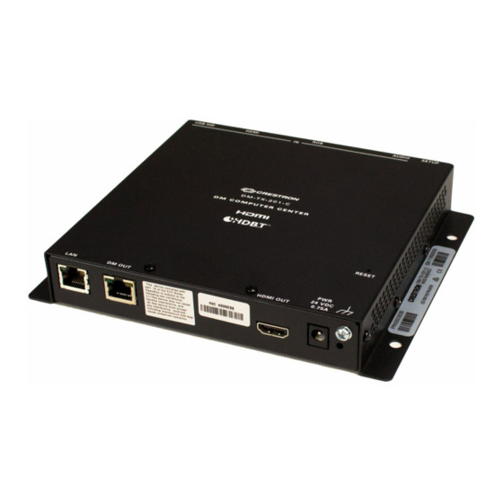
Physical Description The following sections provide information about the connectors, controls, and indicators that are available on the top, front, and rear of the DM-TX-201-C. Top View The following illustration shows the top of the DM-TX-201-C. Top View RESET: Recessed push button for hardware reset ... -
Page 7: Front View
Connects to the DM 8G+ input of a DM switcher, receiver/room controller, or other ® DM device, or to an HDBaseT device via CAT5e or Crestron DM-CBL-8G cable; Green LED indicates DM link status; Solid amber LED indicates HDCP video;... -
Page 8: Rear View
The RGB input can accept component, composite, and S-Video signals through an appropriate adapter (not included) or via direct interface to the Crestron MPS Series products. However, input sync detection is not provided for composite or S-Video signal types through this connection. -
Page 9: Communications Using Crestron Toolbox Software
TCP/IP provides a faster method of communications than USB and is required for operation with a Crestron control system. Using USB Communications Use Crestron Toolbox software to establish USB communications between a PC and a DM switcher. NOTE: The Type A to Type B USB cable included with a DM switcher connects the USB port on a PC to the COMPUTER port on the DM switcher. -
Page 10: Using Tcp/Ip Communications
3. In the drop-down list at the bottom of the System Info window, select the entry of the DM switcher. Device information is displayed. Using TCP/IP Communications Use Crestron Toolbox software to establish TCP/IP communications between a PC and a DM switcher. TCP/IP Communications via a DM Switcher... -
Page 11: Communications Via The Lan Port Of The Dm-Tx-201-C
Communications via the LAN Port of the DM-TX-201-C Use Crestron Toolbox software to establish TCP/IP communications between a PC and a DM-TX-201-C via the LAN port of the DM-TX-201-C. In this scenario, the DM-TX-201-C is used in a stand-alone configuration in which it does not connect to a DM switcher. -
Page 12: Ip Table Configuration
If the DM-TX-201-C connects to a DM switcher, the IP table of the DM-TX-201-C is created automatically. To create the IP table of the DM-TX-201-C in a stand-alone configuration, use Crestron Toolbox software and do the following: 1. Using the Device Discovery Tool, find the IP address of the DM-TX-201-C. -
Page 13: Firmware Upgrade
Firmware Upgrade The latest firmware file (*.puf) can be downloaded from the Crestron website after logging in to the website as an authorized user. To upgrade firmware, use the Crestron Toolbox software and do the following: 1. Depending on whether the DM-TX-201-C connects to a DM switcher, do either of the following: •... -
Page 14: Troubleshooting
Troubleshooting The following table provides troubleshooting information. If further assistance is required, contact a Crestron customer service representative. DM-NVX Troubleshooting TROUBLE POSSIBLE CAUSE(S) CORRECTIVE ACTION The Power LED does not The device is not receiving If the device is powered using illuminate. -
Page 15: Appendix: Pin Assignments
Appendix: Pin Assignments This section provides information about pin assignments and wiring for the following connectors: • RGB IN • DM OUT • RGB IN Pin Assignments Pin 5 Pin 1 NUMBER YPbPr S-Video Composite Pin 10 Pin 6 Pin 15 Pin 11 COMP RED_GND Pr_GND... - Page 16 Crestron Electronics, Inc. Supplemental Guide – DOC. 6958D 15 Volvo Drive Rockleigh, NJ 07647 (2027158) Tel: 888.CRESTRON 09.17 Fax: 201.767.7576 Specifications subject to www.crestron.com change without notice.
Need help?
Do you have a question about the DigitalMedia 8G+ DM-TX-201-C and is the answer not in the manual?
Questions and answers