Advertisement
INSTALLATION
line.The 4 motors can be operated locally in one group by a local switch. Several push buttons and units can be connected
in parallel.
Two previously recorded intermediate positions can be called-up via an optional button ("IP key"). By connecting a switch, it is
possible to disconnect the automatic mode. All the safety commands, which are activated by the BUS line, have priority even
when the automatic mode is disconnected. The BUS line is powered directly by the CD 1 x 4 P.
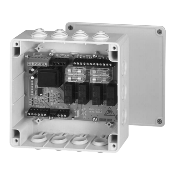
The CD 1 x 4 P can be installed whether surface-mounted, in false floors, partition walls or false ceilings, or in an electrical
cabinet with a special DIN rail adapter.
1
Installation
ATTENTION : observe precaution for handling electrostatic discharge sensitive devices.
The printed circuit board is packed in an anti-static protective covering upon delivery.
Assembly, testing, commissioning and trouble-shooting of the unit may only be carried out by a qualified electrician (respect the local
electrical standard). Disconnect all the connection wires which are to be fitted. Take the necessary safety measures to prevent uninten-
tional reconnection.
Proper functioning can only be guaranteed by expert installation and sufficient power supply.
1.1 Assembly / Wiring
CD 1 x 4 P6 for the DIN rail
When fitting the CD 1 x 4 P6 board on 35 mm DIN rail, two DIN rail adapters are used.
Put the board on the adapter and then clip the adapter onto the DIN rail.
When installing the unit in an electrical cabinet, please observe that a protection must be used to prevent direct access to the electri-
cally conductive components.
CD 1 x 4 P8 for surface-mounting
The board is screwed into a IP 54 box and can be installed in false ceilings, partition walls or false floors in damp rooms.
Connection wires:
max. 2.5 mm2 rigid wires or 1.5 mm2
stranded wires
PE (x6): Earth (all PEs are bridged)
L/N (x2) :Mains (both L and N are bridged)
M1 to M4: N/ /
(x4)
Motors 1 to 4
Local 1: A /+/ / /IP
on/off switch for all 4 motors (optional)
local switch (up/down/stop) for all 4 mo-
tors
local swirch for the intermediate position
("IP key") for all 4 motors (optional)
Bus 20 V:
/ /COM (x2)
IB Bus line (coming and going)
SW1:
Dipswitch for selecting roller
shutters/awnings (ON)
or Venetian blinds (OFF) for all 4 motors.
CD 1 X 4 P
The CD 1 x 4 P enables the individual control of 4 x 230 V AC motors. As the CD 1 x 4 P can be
used as local and master control, it is suitable for large and small installations. An additional group
control is no longer necessary with the CD 1 x 4 P.
The CD 1 x 4 P is suitable for roller shutters, awnings, as for exterior and interior Venetian blinds.
The slat rotation is adjustable.
General control is activated by IB compatible control units (such as e.g. a timer control, solar
and wind control or façade control) and transferred to all CD 1 x 4 P via the IB low voltage BUS
Jonction Box
Live (L)
Neutral (N)
Ground (PE)
Mains
230V 50Hz
Mains
Control
system
Dry contacts control system :
Soliris IB
Chronis IB
Centralis IB
Outputs MCII
Local group control
motors 1 to 4
Four motors control unit
Motor 1
Motor 2
Motor 3
Motor 4
CD 1x4 P
ON
SW1
guide
Motor 5
Motor 6
Motor 7
Motor 8
CD 1x4 P
ON
SW1
IB Bus line
Local group control
motors 5 to 8
to other CD 1x4 P
motor conrol units
Advertisement
Table of Contents

Related Manuals for SOMFY CD 1 x 4 P6


Summary of Contents for SOMFY CD 1 x 4 P6
- Page 1 CD 1 x 4 P6 for the DIN rail When fitting the CD 1 x 4 P6 board on 35 mm DIN rail, two DIN rail adapters are used. Put the board on the adapter and then clip the adapter onto the DIN rail.
- Page 2 Local operation of the 4 motors is carried out via the local switch connected to the unit. Several local switches can be connected in parallel. Switches supplied by switch manufacturers as well as the SOMFY Centralis IB switch can ensure local operation. - Connect the local switch (see wiring diagram) - Press the corresponding key to move the motors UP or DOWN.
- Page 3 Intermediate position With roller shutters and awnings The 4 motors can be moved to one or two selected intermediate positions. The recording and the calling-up of an intermediate position can only be carried out by activating a connected “IP key” (see wiring diagram). The first intermediate position is recorded from the upper end limit position of the system (shutter/awning up).
-
Page 4: Technical Data
With box : IP 54 Protection class Running time (switching time of relay) Approx. 3 minutes EN 60730-1; EN 50081-1; EN50082-1 SOMFY SAS, capital 20.000.000 Euros, RCS Bonneville 303.970.230 All rights reserved to make changes without prior notice. ©SOMFY. GMD021010...
Need help?
Do you have a question about the CD 1 x 4 P6 and is the answer not in the manual?
Questions and answers