Table of Contents
Advertisement
Quick Links
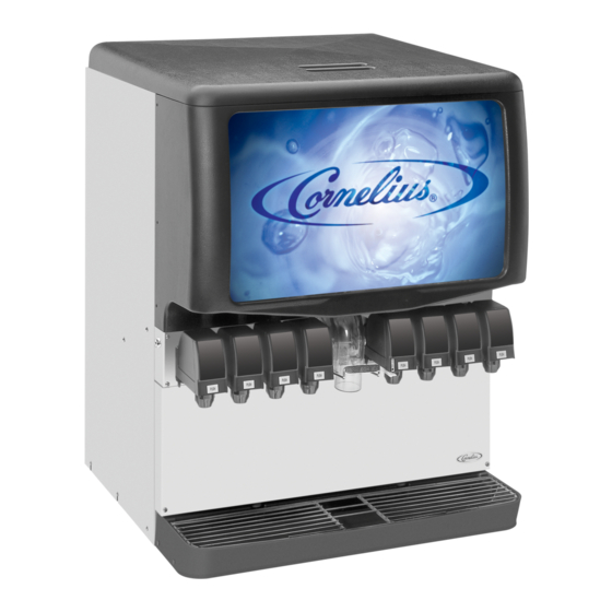
Installation Manual
ICE/BEVERAGE DISPENSER
Model: Enduro-200/250
IMPORTANT:
TO THE INSTALLER.
It is the responsibility of
the Installer to ensure that
the water supply to the
dispensing equipment is
provided with protection
against backflow by an air
gap as defined in
ANSI/ASME A112.1.2-1979;
or an approved vacuum
breaker or other such
method as proved effective
by test.
Water pipe connections
and fixtures directly
connected to a potable
water supply shall be
sized, installed, and
maintained according to
Federal, State, and Local
Codes.
Part No. 92181INS
March 24, 2004
Revised: April 14, 2009
Revision: E
THIS DOCUMENT CONTAINS IMPORTANT INFORMATION
This Manual must be read and understood before installing or operating this equipment
www.cornelius.com
1
92181INS
Advertisement
Table of Contents

Subscribe to Our Youtube Channel
Related Manuals for Cornelius Enduro-200


Summary of Contents for Cornelius Enduro-200
- Page 1 Installation Manual ICE/BEVERAGE DISPENSER Model: Enduro-200/250 IMPORTANT: TO THE INSTALLER. It is the responsibility of the Installer to ensure that the water supply to the dispensing equipment is provided with protection against backflow by an air gap as defined in ANSI/ASME A112.1.2-1979;...
-
Page 2: Table Of Contents
TABLE OF CONTENTS Page SAFETY PRECAUTIONS ........... DESCRIPTION . -
Page 3: Safety Precautions
SAFETY PRECAUTIONS Always: Disconnect power to the dispenser before servicing or cleaning. Never: Place hands inside of hopper or gate area without disconnecting power to the dispenser. Agitator rotation oc- curs automatically when dispenser is energized! This ice dispenser has been specifically designed to provide protection against personal injury and eliminates contamination of ice.To insure continued protection and sanitation, observe the following: ALWAYS: Be sure the removable lid is properly installed to prevent unauthorized access to the hopper interior and possible contamination of the ice. -
Page 4: Installation Instructions
INSTALLATION INSTRUCTIONS 1. Locate the dispenser indoors on a level counter top. LEG OPTION Note: Before installing legs, the plastic plugs must be removed. Unpack the four (4) legs and install them into the threaded holes provided in the bottom of the unit. The in- staller must provide flexibility in the product and utility supply lines to permit shifting the position of the dis- penser sufficiently to clean the area beneath it. -
Page 5: Gate Restrictor Plate Adjustment
GATE RESTRICTOR PLATE ADJUSTMENT CAUTION: Disconnect power to dispenser before installing, removing or adjusting restrictor. The restrictor plate may be adjusted up or down as shown in Figure 2 to reduce or increase the ice dispensing rate, especially desirable when using glasses or other containers with small openings. Adjustment can be made by sliding the restrictor plate up or down with nuts loosened, to obtain the desired ice dispensing rate. -
Page 6: Figure 2. Gate Restrictor Plate
INSTALL PLATE ON STUDS AS SHOWN FIGURE 2. GATE RESTRICTOR PLATE 7/16 DIA. 1 13/16 26 7/16 1 5/16 18 5/8 21 1/4 30 11/16 23 1/16 3 1/2 9 3/16 11 5/8 Z Style REMOVABLE SINK TO FRONT OF DRIP RECOMMENDED COUNTER OPENING SIZE TRAY ON COUNTERTOP 9 X 12 FOR UTILITIES AND BEVERAGE... -
Page 7: Figure 4. Flow Diagram ("Bc" Unit With Six Beverage Faucets)
FAUCETS VIEWED FROM THIS SIDE FIGURE 4. FLOW DIAGRAM (UNIT WITH SIX FAUCETS) 92181INS... -
Page 8: Figure 5. Flow Diagram ("Bc" Unit With Eight Beverage Faucets)
FAUCETS VIEWED FROM THIS SIDE FIGURE 5. FLOW DIAGRAM (UNIT WITH EIGHT FAUCETS) 92181INS... -
Page 9: Figure 6. Flow Diagram ("Bc" Unit With Ten Beverage Faucets)
FAUCETS VIEWED FROM THIS SIDE FIGURE 6. FLOW DIAGRAM (UNIT WITH TEN FAUCETS) 92181INS... -
Page 10: Figure 7. Flow Diagram ("B" Unit With Eight Beverage Faucets)
FAUCETS VIEWED FROM FRONT OF UNIT FIGURE 7. FLOW DIAGRAM (”B” UNIT WITH EIGHT BEVERAGE FAUCETS) 92181INS... -
Page 11: Figure 8. Wiring Diagram (115 Volt Unit)
92181INS... -
Page 12: Figure 9. Schematic (115 Volt Unit)
TIMER RECTIFIER MOTOR HEATER AGITATOR MOTOR N.O. START CAPACITOR VEND SWITCH N.C. CAPACITOR MOTOR START RELAY GATE SOLENOID BALLAST LIGHT STARTER OPTIONAL BEVERAGE TRANSFORMER OPTIONAL FLAVOR VLVS OPTIONAL LOW ICE LEVEL LIGHT T’STAT KEYPAD BOARD SOLENOIDS OPTIONAL OPTIONAL BEVERAGE BEVERAGE VALVES VALVES BEVERAGE PANEL... -
Page 13: Figure 10. Wiring Diagram (220--240 Volt Unit)
FLAVOR SOLENOIDS 1 2 3 4 92181INS... -
Page 14: Figure 11. Schematic (220--240 Volt Unit)
EMI FILTER LINE FILTER TIMER RECTIFIER MOTOR HEATER POWER SWITCH AGITATOR MOTOR N.O. VEND SWITCH START CAPACITOR N.C. MOTOR START RELAY GATE SOLENOID OPTIONAL BALLAST OPTIONAL LIGHT OPTIONAL STARTER OPTIONAL BEV. TRANSFORMER OPTIONAL BEV. TRANSFORMER OPTIONAL FLAVOR VLVS KEYPAD BOARD SOLENOIDS BEV. -
Page 15: Troubleshooting
TROUBLESHOOTING IMPORTANT: Only qualified personnel should service internal components or electrical wiring. WARNING: If repairs are to be made to a product system, remove quick disconnects from the applicable product tank, then relieve the system pressure before proceeding. If repairs are to be made to the CO system, stop dispensing, shut off the CO supply, then relieve the... -
Page 16: Beverage Not Sweet Enough
Trouble Probable Cause BEVERAGE NOT SWEET ENOUGH. A. Empty syrup tank. B. Faucet brix requires adjusting. BEVERAGES NOT COLD (UNITS WITH BUILT-IN A. Unit standing with no ice in hopper or no ice in cold COLD PLATE). plate cabinet. FLAVOR SYRUPS DO NOT DISPENSE. A. -
Page 17: Warranty
WARRANTY IMI Cornelius Inc. warrants that all equipment and parts are free from defects in material and workmanship under normal use and service. For a copy of the warranty applicable to your Cornelius product, in your country, please write, fax or telephone the IMI Cornelius office nearest you. Please provide the equipment model number and the date of purchase.
Need help?
Do you have a question about the Enduro-200 and is the answer not in the manual?
Questions and answers