Advertisement
Quick Links
Advertisement

Related Manuals for LINK-MI LM-TV09S


Summary of Contents for LINK-MI LM-TV09S
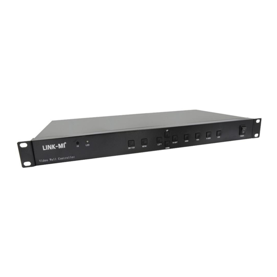
- Page 1 LM-TV09S LM-TV Serial Irregular Video Wall controller User Manual...
-
Page 2: Table Of Contents
Catalog Device installation..............................2 Software Communication Settings.......................... 3 Software Key Functions............................6 image Debugging..............................8 Buttons and Remote Control Instructions......................14 Serial Port Control Code............................ 15... -
Page 3: Th Device Installation
Device installation 1, the installation instructions In order to save your precious time, this manual does not introduce common sense of common use of electrical appliances, please follow the common sense of common electrical appliances; Before using the device, please read the operating instructions carefully so that you can quickly become familiar with the commissioning and use of the device. - Page 4 , Product Description The LM-TV09S is a very flexible shaped splicing processor. It can make a creative irregular splicing for horizontal screen. The biggest feature of the product is that it can freely capture any part of the input signal to a single LCD unit through remote control.
- Page 5 2.4, Vertical or Horizontal irregular splicing Support irregular splicing for both vertical or horizontal when using a vertical screen rotator.
- Page 6 As shown in the following figure: 2.6, Mirror Function LM-TV09S shaped splicer can freely mirror left and right for each LCD screen, mirror up and down you, and flip 180 degrees, so as to achieve personalized mirror stitching, as shown in the figure:...
-
Page 7: Th Software Communication Settings
Software Communication Settings For the first time, the alien splicing processor needs to be debugged by software according to the actual arrangement of the LCD screen. Before the debugging, the control software and the device need to communicate normally. The following is the communication setting mode: Open the Software folder inside the CD and copy it to the computer hard disk , open the VideoWallcontrol.exe file inside, and then pop up the following interface;... - Page 8 Setting: set the serial port number Connect: Connect the serial port Disconnect: Disconnect the serial port 1920x1080: Set the output resolution Save: Save the settings of the settings Load: call the saved setup parameters ▽: Language settings Buttons in the Input group: HDMI: One button to switch to HDMI signal input;...
-
Page 9: Th Image Debugging
image Debugging Note: This description describes the special-shaped splicing debugging method, but because the special-shaped splicing is different from the regular splicing, it takes a certain time in the actual operation to fine-tune the image to achieve the best effect of the splicing. The following is an example of the splicing operation steps: 1. - Page 10 To complete the debugging of one of the following special-shaped 2 stitching as an example: (This image is HDMI signal input, the debug image is the above USB input as an example) 5. Define the signal input to the splicing processor as an image with a length of 1920 pixels and a height of 1080 pixels. The upper left corner is the starting point 0 of the horizontal X and the vertical Y, as shown in the following figure: 3.2, Estimate the starting point of the coordinates and the width and height of the image as follows:...
- Page 11 3.3. After opening the control software to connect to the serial port, set Add info to ON state. Each display unit displays the corresponding address and other information as follows: 3.4. Set Splice to the on state, hold down the left mouse button and drag inside the software interface to create a window similar to the estimated coordinates and length and width, as shown below: 3.5, Use the right mouse button to click the dragged window, the following interface pops up, and the ID address is modified to the ID corresponding to the display unit in the interface.
- Page 12 3.6, The size and position of the window can be adjusted by the mouse to adjust the image content displayed by each display unit in the alien stitching. At the same time, the coordinates and the length and width can be precisely adjusted by Position. When the left mouse button is selected, the arrow keys of the keyboard can be realized by the arrow keys of the keyboard.
- Page 13 3.6.2 Through the Position to precisely adjust the coordinates and length, width and left click on the selected window, through the keyboard's direction key to achieve the overall movement of the window to control the display unit, these two methods, can be based on the previous step to eliminate the artificial stretching window Brought a subtle gap.
- Page 14 Convert the input signal to an HDMI input: 3.7, Mirror adjustment, click on Rotate to mirror the image of the LCD unit to the left and right, mirror up and down, and rotate 180 degrees to adjust. Mirroring left and right: Mirror up and down: Rotate 180 degrees: 3.8, Debug the output resolution of the corresponding display unit via Resolution.
-
Page 15: Th Buttons And Remote Control Instructions
Buttons and Remote Control Instructions Note: Using the buttons and the remote control to set up the profile stitching will become very complicated. Please use the control software for debugging. This manual will only briefly explain the remote control and chassis buttons. 1, chassis button function description Switch: splicing on/off;... -
Page 16: Th Serial Port Control Code
Serial Port Control Code 1, the product is controlled by RS-232 serial port, the following is the definition of device RJ-45 carrier TX, RX, grounding: 2. In addition to using the control software to control the device, the user can also control the device by issuing some commands to the device through the central control. - Page 17 SHENZHEN LINK-MI TECHNOLOGY CO.,LTD WWW.LINK-MI.COM E-mail: sales@link-mi.com...
Need help?
Do you have a question about the LM-TV09S and is the answer not in the manual?
Questions and answers