Table of Contents
Advertisement
Quick Links
Advertisement
Table of Contents

Subscribe to Our Youtube Channel
Related Manuals for LINK-MI LM-TV06M


Summary of Contents for LINK-MI LM-TV06M
- Page 1 LM-TV06M 2x3 Video Wall Controller User Manual...
-
Page 2: Table Of Contents
Catalog Preface ......................1 Notices ......................1 Product Introduction ................2 Specification ..................3 Topological Graph ................4 Ports and Keys ..................4 1. Rear Panel Interface Description ............4 2. Front Panel Description ............... 5 3. Remote Control Button Description ............ 5 Function Description ................ -
Page 3: Preface
Preface Thanks for choosing our products! For the safety of both of yourself and the equipment, please read the instruction manual carefully before using this equipment. Products are covered with a fragile label, please preserve it carefully which will serve as the warranty certificate. -
Page 4: St Product Introduction
This product is a HD screen splicing processor special designed for LCD TV, ultra narrow LCD screen, projector. A single device supports 4 to 12 HDMI Outputs (LM-TV06M is with 6 HDMI outputs) to connect with LCD TV or other display units. User can customize a variety of splicing mode according to their need. -
Page 5: Nd Specification
1x4, 1x3, 1x2 ... splicing mode; HDMI Output *6 single maximum support for the 12 HDMI signal outputs (LM-TV06M is with 6 HDMI outputs); maximum resolution: support 1920x1080@60Hz 3.5 audio interface, support stereo, audio and video Audio Output *1... -
Page 6: Rd Topological Graph
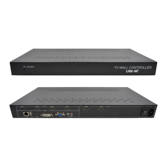
Topological Graph Ports and Keys 1. Rear Panel Description Interface Input Output... -
Page 7: Front Panel Description
• DC12V:12V Power In • HDMI 1:HDMI 1 Output • RS232: RS232 In • HDMI 2:HDMI 2 Output • USB: USB Input • HDMI 3:HDMI 3 Output • HDMI: HDMI Input • HDMI 4:HDMI 4 Output • DVI: DVI Input •... - Page 8 Power OFF Power ON PC-RGB Signal HDMI HDMI Signal DVI Signal Volume Up Subtitle ON/OFF Volume Down SW/SP Splicing/Single INPUT Signal Source Menu ← Left → Right ↑ ↓ Down MENU MENU EXIT EXIT MUTE MUTE UPGRADE UPGRADE...
-
Page 9: Th Function Description
Function Description 1. 2x3 Splicing Mode Setting Up Description (Note: This instruction takes 2x2 splicing as an example, 2x3 splicing operation is the same.) Connect input signal (HDMI, DVI, VGA) to the input port of the splicing box. Connect the HDMI output of the splicing box to display screen (no need to be in a certain order Connection). -
Page 10: Main Menu Description
After above adjustment, set the Splice "on", that is the end of splicing setting. See picture below: 2. Main Menu Description... - Page 11 Menu 1:Picture Menu Menu 2:Audio Menu Menu 3:Time Menu...
-
Page 12: Splicing Wall Setting Up
Menu 4:Option Menu 3. Splicing Wall Setting up In the main menu, choose to enter into the Set Up menu - > Splicing Mode Set Up. Press the left and right keys to select the corresponding splicing mode. -
Page 13: Parameter Description
Select the HDMI port, and select the corresponding splicing position (curtain wall address) according to the port ID. Set the splicing switch to “on”, then you can start the splicing. 4. Parameter Description HDMI Port: The ID number of connected HDMI outputs should be corresponding to the splicing position to make the splicing correctly. - Page 14 enter the LED function. See picture below. Under LED SET menu, user can set corresponding LED function like image zoom in/out and cutting. See picture below: LED Setting...
-
Page 15: Flying Subtitle Description
LED Image Scaling DISP HSTAR: Select the X axis starting point for the zoomed image DISP VSTAR: Select the Y axis starting point for the zoomed image DISP WIDTH: Select the width of the zoomed image DISP HEIGHT: Select the height of the zoomed image LED Image Clipping CROP HSTAR: Select the X axis coordinates for the cutting position CROP VSTAR: Select the Y axis coordinates for the cutting position... - Page 16 Connect the RS232 cable to the RS232 interface of the product, open corresponding rolling subtitle software to set rolling subtitle; In this software, user can make all subtitle function settings, such as text location, text size, font speed, text color, background color...etc; Can also adjust LED function, LED image scaling and LED images cutting function, see below picture:...
-
Page 17: Th Common Problems And Solution
Common Problems and Solution 1. When the wiring is completed and started up the device, screen shows "no signal". a. Please check whether the signal cable is plugged in. b. Try restart the device to recapture the signal. c. Try to replace the signal cable. 2. -
Page 18: Th Guarantee Description
a. Check whether the input and output signal cable is normal. b. Check whether the display units works normally. 5. When the menu is not available (No menu pop-up). a. Check if the caption function is off (The menu will be unavailable when caption function is on) Guarantee Description Note: From the date of purchase, user enjoy one year free warranty service, not... - Page 19 SHENZHEN LINK-MI TECHNOLOGY CO., LTD. WWW.LINK-MI.COM E-mail: sales@link-mi.com...
Need help?
Do you have a question about the LM-TV06M and is the answer not in the manual?
Questions and answers