Table of Contents
Advertisement
Available languages
Available languages
Quick Links
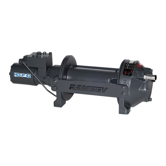
MODEL HD-P 42, 2 PLANETARY WINCH
INTENDED USE: VEHICLE RECOVERY AND PULLING OF LOADS
CAUTION: READ AND UNDERSTAND THIS MANUAL BEFORE INSTALLATION AND
OPERATION OF WINCH. SEE WARNINGS!
Ramsey Winch Company
P.O. Box 581510 - Tulsa, OK 74158-1510 USA
Phone: (918) 438-2760 - Fax (918) 438-6688
Visit us at http://www.ramsey.com
Ramsey Authorized Representative in the Community
(Please contact for regulatory inquiries only.)
OPERATING, SERVICE AND
MAINTENANCE MANUAL
English (
Original Instructions
Français (
Traduction des instructions originales)
Deutsch (
Übersetzung der Originalanleitung
Español(
Traducción de las instrucciones originales
Alura Group BV
P.O. Box 18626
2502 EP The Hague
The Netherlands
Tel: (31) (0) 70 362-4896
Fax: (31) (0) 70 346-7299
) . . . . . . . . . . . . . .
) . . . . . 37
OM-914261-1014-C
1
. . . 18
). 56
Advertisement
Chapters
Table of Contents

Related Manuals for Ramsey Winch HD-P 42


Summary of Contents for Ramsey Winch HD-P 42
- Page 1 Übersetzung der Originalanleitung Español( ). 56 Traducción de las instrucciones originales MODEL HD-P 42, 2 PLANETARY WINCH INTENDED USE: VEHICLE RECOVERY AND PULLING OF LOADS CAUTION: READ AND UNDERSTAND THIS MANUAL BEFORE INSTALLATION AND OPERATION OF WINCH. SEE WARNINGS! Ramsey Winch Company P.O.
- Page 2 OM-914261-1014-C...
- Page 3 Nous déclarons par la présente que le modèle de treuil with the following directive provided that the USER complies HD-P 42, 2 est conforme à la directive suivante, sous réserve que with all responsibilities described in the Owner’s Manual: l’UTILISATEUR ait assumé toutes les responsabilités figurant dans 2006/42/EC le manuel de l’utilisateur :...
-
Page 4: Table Of Contents
TABLE OF CONTENTS NTRODUCTIONS ............................. 3 USER’S RESPONSIBILITY FOR CE COMPLIANCE .................... 3 SPECIFICATIONS ............................. 3 WARNINGS ..............................3 WINCH MOUNTING ............................4 ROPE INSTALLATION ............................4 MAINTENANCE ..............................5 OPERATION ..............................5 HYDRAULIC SYSTEM REQUIREMENTS ......................6 TYPICAL LAYOUT ............................6 PERFORMANCE CHARTS .......................... -
Page 5: User's Responsibility For Ce Compliance
SPECIFICATIONS AND WARNINGS SPECIFICATIONS* First Layer Line Pull …………………………… 42,2 kN (9480 lb) Noise Level ….…………. …………………………… 79 db Ambient Temperature Range ……………… -28C to 60C ……………… (-20F to 140F) Gear Reduction …………………………………… 5:1:1 Weight (without rope) ………… 39.5 kg (87 lb) STD DRUM LAYER OF ROPE... -
Page 6: Winch Mounting
WINCH MOUNTING/ROPE INSTALLATION WINCH MOUNTING ESSENTIAL MOUNTING INSTRUCTIONS TO MAINTAIN ALIGNMENT OF PLANETARY WINCH COMPONENTS: CAUTION: If longer bolts (minimum grade 5) are substituted to mount winch or to mount a roller guide at the side mount pads, bolt length must be such as to allow between 12,7mm (.50 in) and 17,5 mm (.68 in) thread length engagement in the tapped holes in side of each end bearing. -
Page 7: Maintenance
MAINTENANCE ROPE DRUM ROPE DRUM ROTATION DIRECTION ROTATION DIRECTION PLUG POSITION CARTRIDGE CARTRIDGE POSITION (REEL IN) RAISE INLET POSITION "A" ROTATION "B" ROTATION CAUTION: OVER- TIGHTENING OF JAM NUT MAY STRIP NYLON SETSCREW. MAINTENANCE 1. Inspect the rope for damage and lubricate frequently. If the rope becomes frayed with broken strands, replace immediately. -
Page 8: Hydraulic System Requirements
HYDRAULIC SYSTEMS Refer to the performance charts below to properly match your hydraulic system to the winch performance. The charts consist of: (1) Line Pull first layer kN (lb) vs. Working Pressure bar (PSI). (2) Line Speed, first layer MPM (FPM) vs. flow LPM (GPM). HYDRAULIC SYSTEM REQUIREMENTS Motor spool (open center) control valve 2. -
Page 9: Troubleshooting Guide
TROUBLESHOOTING GUIDE CONDITIONS POSSIBLE CAUSE CORRECTION/ACTION DRUM WILL NOT Winch not mounted squarely, causing end Check mounting. Refer to Winch Mounting, ROTATE AT NO LOAD bearing to bind up page 4. Gears damaged Inspect and replace damaged gears DRUM WILL NOT Winch not mounted squarely, causing end Check mounting. -
Page 10: End Of Service Measures
END OF SERVICE MEASURES When winch reaches the end of it’s serviceable life, dispose of per local environmental regulations. INSTRUCTIONS FOR OVERHAUL HD-P 42,2 SERIES WINCH Take note of mounting configurations for proper mounting of parts during re-assembly. Replace all gaskets, o-rings, and seals during re-assembly. - Page 11 Remove seal (item #37) from gear housing end bearing (item #9). Loosen nut (item #20) and remove nylon setscrew (item #17). Remove ring gear from gear housing end bearing, if necessary. Remove bushing (item #12) from end bearing. Press new bushing into end bearing. Install ring gear, then nylon setscrew and nut.
- Page 12 Set winch with gear housing end down on work surface. Install well-oiled o-rings and backup rings into grooves on outside of brake piston and backup brake piston as shown in cross-section A-A below. Piston, backup piston, brake discs and stators must be clean and free of grease and oil. Insert brake discs (item #4) and stators (item #3) into gear end alternating, with stators first and last.
- Page 14 HD-P 42,2 AIR SHIFT...
- Page 15 HD-P 42,2 BLOCKED CLUTCH...
- Page 16 HD-P 42,2 MANUAL SHIFT...
- Page 17 HD-P 42,2 MANUAL SHIFT PARTS LIST Item No. Quantity Part No. Description 234224 DRUM ASSY STD 234234 DRUM ASSY "Y" 276048 SHIFTER ASSY 330011 STATOR-BRAKE 330012 DISC-BRAKE 330013 PISTON-BRAKE 330014 PISTON-BACKUP BRAKE 334174 GEAR-OUTPUT, SUN 338358 END BEARING-MOTOR 338327 END BEARING- GEAR HOUSING...
- Page 18 HD-P 42,2 AIR SHIFT...
- Page 19 HD-P 42,2 AIR SHIFT PARTS LIST Item No. Quantity Part No. Description 234224 DRUM ASSY STD 234234 DRUM ASSY "Y" 236020 LIGHT ASSY 276058 SHIFTER ASSY 312529 BRACKET-LIGHT ASSY 330011 STATOR-BRAKE 330012 DISC-BRAKE 330013 PISTON-BRAKE 330014 PISTON-BACKUP BRAKE 334174 GEAR-OUTPUT, SUN...
- Page 21 Item No. Quan ty Part No. Descrip on 234224 DRUM ASSY STD 234234 DRUM ASSY "Y" 299693 PLUNGER ASSY 330011 STATOR-BRAKE 330012 DISC-BRAKE 330013 PISTON-BRAKE 330014 PISTON-BACKUP BRAKE 334174 GEAR-OUTPUT, SUN 338358 END BEARING-MOTOR 338327 END BEARING-GEAR HOUSING 357177 SHAFT-INPUT STD DRUM 357176 SHAFT-INPUT "Y"...
- Page 22 Español( ). 56 Traducción de las instrucciones originales TREUIL PLANÉTAIRE MODÈLE HD-P 42,2 UTILISATION PRÉVUE : DÉPANNAGE DE VÉHICULE ET TRACTION DE CHARGES MISE EN GARDE : ASSUREZ-VOUS DE LIRE ET DE COMPRENDRE CE MANUEL AVANT D’INSTALLER ET D’UTILISER LE TREUIL. LISEZ LES AVERTISSEMENTS ! Ramsey Winch Company P.O.
- Page 23 TABLE DES MATIÈRES INTRODUCTIONS ........................23 RESPONSABILITÉ DE L’UTILISATEUR POUR CONFORMITÉ AUX NORMES CE ....23 CARACTÉRISTIQUES TECHNIQUES ..................23 AVERTISSEMENTS ........................23 FIXATION DU TREUIL ........................ 24 POSE DU CÂBLE ........................24 ENTRETIEN ..........................25 FONCTIONNEMENT ........................25 CARACTÉRISTIQUES DU SYSTÈME HYDRAULIQUE ............26 INSTALLATION TYPE ........................
-
Page 24: Responsabilité De L'utilisateur Pour Conformité Aux Normes Ce
CARACTÉRISTIQUES TECHNIQUES Traction du câble, première couche …………………………… 42,2 kN (9480 lb) Niveau sonore ….…………..….……… … ………………………… 79 db Plage de température ambiante …………………………… -28C to 60C …………………………… (-20F to 140F) Démultiplication ……………………………………… 5:1:1 Poids (sans le câble) TAMBOUR STD.……… 39,5 kg (87 lb) COUCHE DE CÂBLE 42,2... -
Page 25: Fixation Du Treuil
FIXATION DU TREUIL / POSE DU CÂBLE FIXATION DU TREUIL NSTRUCTIONS DE MONTAGE IMPORTANTES POUR MAINTENIR L’ALIGNEMENT DES ÉLÉMENTS DU TREUIL PLANÉTAIRE : MISE EN GARDE : En cas d'utilisation de boulons plus longs (grade 5 minimum) Ce treuil doit absolument être monté correctement afin que les pour la fixation du treuil ou d'un guide à... -
Page 26: Entretien
ENTRETIEN SENS DE ROTATION DU SENS DE ROTATION DU TAMBOUR TAMBOUR POSITION DU BOUCHON POSITION DE ENTRÉE CORRESPONDANT POSITION DE LA CARTOUCHE LA CARTOUCHE À L'ENROULEMENT SENS DE ROTATION « A » SENS DE ROTATION « B » ENTRETIEN 1. Examinez l’état du câble et lubrifiez-le fréquemment. Tout câble effiloché ou comportant des brins brisés doit être remplacé... -
Page 27: Caractéristiques Du Système Hydraulique
CARACTÉRISTIQUES DU SYSTÈME HYDRAULIQUE Reportez-vous aux diagrammes de performances ci-dessous pour établir une correspondance entre votre système hydraulique et le fonctionnement de votre treuil. Ces diagrammes sont constitués des éléments suivants : (1) Traction du câble, première couche kN (lb) vs. Pression de service, bars (PSI). (2) Vitesse du câble, première couche M/MIN (PI/MIN) vs. -
Page 28: Guide De Résolution Des Problèmes
GUIDE DE RÉSOLUTION DES PROBLÈMES PROBLÈME CAUSE PROBABLE MESURE CORRECTIVE LE TAMBOUR NE TOURNE Treuil mal monté, ce qui entraîne un grippage Vérifiez le montage. Reportez-vous à la rubrique Fixation PAS EN L’ABSENCE du tambour par le palier d’extrémité. du treuil en page 24. DE CHARGE. -
Page 29: Fin De La Procédure D'entretien
Quand le treuil arrive à la fin de sa durée de vie, débarrassez-vous en en respectant les règlements locaux de protection de l’environnement. INSTRUCTIONS DE RÉVISION DES TREUILS DE LA GAMME HD-P 42,2 . Prenez note des configurations de montage pour l’assemblage correct des pièces lors du remontage. Remplacez tous les joints statiques, les joints toriques et les joints d’étanchéité... - Page 30 Retirez le joint d’étanchéité (pièce nº 37) du palier d’extrémité de la boîte d’engrenages (pièce nº 9). Desserrez l’écrou (pièce nº 20) et retirez la vis de pression en Nylon (pièce nº 17). Si nécessaire, retirez la couronne du palier d’extrémité...
- Page 31 Placez le treuil sur l’établi avec l’extrémité de la boîte d’engrenages tournée vers le bas. Placez des joints toriques et des bagues d’appui bien huilés dans les rainures, sur l’extérieur du piston de frein et du piston de frein auxiliaire, comme indiqué sur la coupe A-A ci-dessous. Le piston, le piston auxiliaire, les disques de frein et les stators doivent être propres et exempts de graisse et d’huile.
- Page 32 HD-P 42,2 EMBRAYAGE MANUEL...
- Page 33 HD-P 42,2 EMBRAYAGE PNEUMATIQUE...
- Page 34 HD-P 42,2 EMBRAYAGE VERROUILLÉ...
- Page 36 HD-P 42,2 EMBRAYAGE MANUEL - LISTE DES PIÈCES Quantité Nº Réf. Description 234224 TAMBOUR" STD " COMPLET 234234 TAMBOUR" Y " COMPLET 276048 EMBRAYEUR COMPLET 330011 STATOR - FREIN 330012 DISQUE - FREIN 330013 PISTON - FREIN 330014 PISTON - FREIN AUX.
- Page 37 HD-P 42,2 EMBRAYAGE PNEUMATIQUE...
- Page 38 HD-P 42,2 EMBRAYAGE PNEUMATIQUE - LISTE DES PIÈCES Elemento núm. Can dad Pieza núm. Descripción 234224 CONJUNTO DEL TAMBOR ESTÁNDAR 234234 CONJUNTO DEL TAMBOR “Y” 276048 CONJUNTO DEL DESEMBRAGUE 330011 ESTATOR-FRENO 330012 DISCO DEL FRENO 330013 PISTÓN DEL FRENO 330014 PISTÓN DEL FRENO DE RESPALDO...
- Page 39 HD-P 42,2 EMBRAYAGE VERROUILLÉ...
- Page 40 HD-P 42,2 EMBRAYAGE VERROUILLÉ - LISTE DES PIÈCES Quantité Nº Réf. Description 234224 TAMBOUR " STD " COMPLET 234228 TAMBOUR " Y " COMPLET 299693 PISTON EMBRAYAGE COMPLET 330011 STATOR - FREIN 330012 DISQUE - FREIN 330013 PISTON - FREIN 330014 PISTON - FREIN AUX.
- Page 41 Übersetzung der Originalanleitung Español( ). 56 Traducción de las instrucciones originales MODELL HD-P 42,2 HYDRAULISCHE SEILWINDE MIT PLANETENGETRIEBE VERWENDUNGSZWECK: BERGEN VON FAHRZEUGEN UND ZIEHEN VON LASTEN ACHTUNG: VOR DER MONTAGE UND INBETRIEBNAHME DER WINDE MUSS DIESES HANDBUCH GELESEN UND VERSTANDEN WERDEN. SIEHE WARNHINWEISE! Ramsey Winch Company P.O.
- Page 42 INHALTSVERZEICHNIS EINFÜHRUNG ..............................43 ERANTWORTUNG DES BENUTZERS BEZÜGLICH EG-KONFORMITÄT.............. 43 TECHNISCHE DATEN ............................. 43 WARNHINWEISE ............................43 MONTAGE DER WINDE ..........................44 AUFLEGEN DES SEILS ........................... 44 WARTUNG ..............................45 BETRIEB ................................ 45 HYDRAULIKANFORDERUNGEN ........................46 TYPISCHE ANORDNUNG ..........................46 LEISTUNGSDIAGRAMME ..........................
-
Page 43: Erantwortung Des Benutzers Bezüglich Eg-Konformität
TECHNISCHE DATEN* TECHNISCHE DATEN* Seilzugkraft, erste Lage ……………………… 42,2 kN (9480 lb) Lärmpegel ……………………… 79 db Umgebungstemperaturbereich ……………… -28C to 60C ……………… (-20F to 140F) Getriebeuntersetzung ……………………… 5:1:1 Gewicht (ohne Seil) STD. TROMMEL …… 39,5 kg (87 lb) SEILLAGE 42,2 35,2 30,2 Seilzugkraft pro Lage... -
Page 44: Montage Der Winde
MONTAGE DER WINDE MONTAGE DER WINDE WICHTIGE MONTAGEANWEISUNGEN FÜR DIE AUFRECHTERHALTUNG DER AUSRICHTUNG DER PLANETENWINDENKOMPONENTEN: damit die drei Hauptsegmente (Motor, Seiltrommel und Es ist sehr wichtig, dass diese Winde sicher befestigt wird, Getriebegehäuse) richtig ausgerichtet sind. Übermäßiger Buchsenverschleiß und Schwierigkeiten beim Freilauf sind in der Regel Anzeichen von Fehlausrichtung. -
Page 45: Wartung
WARTUNG DREHRICHTUNG DER DREHRICHTUNG DER SEILTROMMEL SEILTROMMEL SCHRAUBENPOSITION (AUFWICKELN) EINLASS PATRONENLAGE ZUGDREHRICHTUNG DER PATRONENLAGE SEILTROMMEL DREHUNG „A" DREHUNG „B" WARTUNG 1. Das Seil auf Beschädigungen überprüfen und regelmäßig schmieren. Ein ausgefranstes oder beschädigtes Seil muss sofort ersetzt werden. 2. Prüfen, ob die Kupplung vollständig einrückt. Siehe obige Anweisungen zum BETRIEB für den jeweiligen Kupplungshebel. -
Page 46: Hydraulikanforderungen
HYDRAULIKANFORDERUNGEN Zur richtigen Wahl der Hydraulik für die Leistung der Winde ist auf die folgenden Leistungsdiagramme Bezug zu nehmen. Die Diagramme zeigen: (1) Seilzugkraft (kN), erste Lage im Vergleich zum Arbeitsdruck (bar). (2) Seilgeschwindigkeit, erste Lage (m/min) im Vergleich zur Förderrate (l/min). HYDRAULIKANFORDERUNGEN 1. -
Page 47: Fehlersuche
FEHLERSUCHE ZUSTAND MÖGLICHE URSACHE ABHILFE/MASSNAHME TROMMEL DREHT SICH Winde nicht gerade montiert, wodurch das Lager Zusammenbau überprüfen. Siehe Montage der Winde NICHT - OHNE LAST eingeklemmt wird. auf Seite 44. Zahnräder beschädigt. Beschädigte Zahnräder inspizieren und ggf. ersetzen. TROMMEL DREHT SICH Winde nicht gerade montiert, wodurch das Lager Zusammenbau überprüfen. -
Page 48: Ausserbetriebsetzung
HD-P 42,2 AUSSERBETRIEBSETZUNG Die Winde am Ende ihrer Brauchbarkeitszeit gemäß örtlichen Umweltvorschriften entsorgen. ANLEITUNG ZUM ÜBERHOLEN DER WINDEN DER MODELLREIHE HD-P 42,2 . Auf die Zusammensetzung der Teile achten, damit diese wieder richtig zusammengebaut werden. Alle Dichtringe, O-Ringe und Dichtungen müssen beim Wiederzusammenbau ersetzt werden. - Page 49 Die Dichtung (Nr. 37) aus dem Getriebekasten-Endlager (Nr. 9) ausbauen. Die Mutter (Nr. 20) lösen und die Nylonstellschraube Nr. 17) entfernen. Falls erforderlich, das Hohlrad vom Getriebekasten-Endlager abnehmen. Die Buchse (Nr. 12) aus dem Endlager ausbauen. Die neue Buchse in das Endlager pressen. Hohlrad, Nylonstellschraube und Mutter wieder anbringen.
- Page 50 Die Winde aufrecht mit dem Getriebekasten nach unten auf eine Werkbank stellen. Gut geölte O-Ringe und Stützringe in die Rillen an der Außenseite des Bremskolbens und Zusatzbremskolbens einsetzen (wie unten im Querschnitt A-A gezeigt). Kolben, Zusatzkolben, Bremsscheiben und Statoren müssen sauber und frei von Schmierfett und Öl sein. Die Bremsscheiben (Nr.
- Page 51 HD-P 42,2 LUFTSCHALTUNG...
- Page 52 HD-P 42,2 HANDSCHALTUNG...
- Page 53 HD-P 42,2 KUPPLUNG VERRIEGELT...
- Page 54 HD-P 42,2 HANDBETÄTIGTE KUPPLUNG...
- Page 55 TEILELISTE FÜR HD-P 42,2 HANDBETÄTIGTE KUPPLUNG Lfd. Nr. Menge Art.-Nr. Beschreibung 234224 STANDARD-TROMMEL, KOMPLETT 234234 „Y“-TROMMEL, KOMPLETT 276048 KUPPLUNGSHEBEL, KOMPLETT 330011 STATOR - BREMSE 330012 SCHEIBE - BREMSE 330013 KOLBEN - BREMSE 330014 KOLBEN - ZUSATZBREMSE 334174 GEAR-OUTPUT, SUN 338358 ENDLAGER - MOTOR 338327 ENDLAGER - GETRIEBEKASTEN 357177 WELLE - ANTRIEB (STD.
- Page 56 HD-P 42,2 PNEUMATISCHE KUPPLUNG...
- Page 57 TEILELISTE FÜR HD-P 42,2 PNEUMATISCHE KUPPLUNG Lfd. Nr. Menge Art.-Nr. Beschreibung 234224 STANDARD-TROMMEL, KOMPLETT 234234 „Y“-TROMMEL, KOMPLETT 236020 LIGHT ASSY 276058 KUPPLUNGSHEBEL, KOMPLETT 312529 HALTERUNG - LAMPENBAUGRUPPE 330011 STATOR - BREMSE 330012 SCHEIBE - BREMSE 330013 KOLBEN - BREMSE 330014 KOLBEN - ZUSATZBREMSE...
- Page 58 HD-P 42,2 KUPPLUNG VERRIEGELT...
- Page 59 TEILELISTE FÜR HD-P 42,2 KUPPLUNG VERRIEGELT Lfd. Nr. Menge Art.-Nr. Beschreibung 234224 STANDARD-TROMMEL, KOMPLETT 234234 „Y“-TROMMEL, KOMPLETT 299693 KUPPLUNG KOLBEN, KOMPLETT 330011 STATOR - BREMSE 330012 SCHEIBE - BREMSE 330013 KOLBEN - BREMSE 330014 KOLBEN - ZUSATZBREMSE 334174 GETRIEBE-AUSGANG, SUN...
- Page 60 Übersetzung der Originalanleitung Español( ). 56 Traducción de las instrucciones originales CABESTRANTE PLANETARIO MODELO HD-P 42,2 USO PRETENDIDO: RECUPERACIÓN DE VEHÍCULOS Y ARRASTRE DE CARGAS PRECAUCIÓN: LEER Y ENTENDER ESTE MANUAL ANTES DE INSTALAR Y OPERAR EL CABESTRANTE. OBSERVAR LAS ADVERTENCIAS.
- Page 61 CONTENIDO INTRODUCCIÓN ..........................RESPONSABILIDAD DEL USUARIO PARA EL CUMPLIMIENTO CON LAS DISPOSICIONES CE ESPECIFICACIONES ........................ADVERTENCIAS..........................MONTAJE DEL CABESTRANTE ....................INSTALACIÓN DE CABLE METÁLICO ..................MANTENIMIENTO .......................... FUNCIONAMIENTO ........................REQUISITOS DEL SISTEMA HIDRÁULICO .................. DISPOSICIÓN TÍPICA ........................GRÁFICOS DE FUNCIONAMIENTO ....................GUÍA DE SOLUCIÓN DE PROBLEMAS ..................
-
Page 62: Responsabilidad Del Usuario Para El Cumplimiento Con Las Disposiciones Ce
ESPECIFICACIONES* ESPECIFICACIONES* Tracción del cable de la primera capa ……………………… 42,2 kN (9480 lb) Nivel sonoro .….…………….………..………...……………. 79 db Temperatura ambiente .…………..……………………… -28C to 60C .…………..……………………… (-20F to 140F) Reducción de engranajes ………………………………… 5:1:1 Peso (sin cable metálico) TAMBOR ESTÁNDAR …… 39,5 kg (87 lb) CAPA DE CABLE 42,2... -
Page 63: Montaje Del Cabestrante
MONTAJE DEL CABESTRANTE MONTAJE DEL CABESTRANTE INSTRUCCIONES DE MONTAJE FUNDAMENTALES PARA ALINEAR LOS COMPONENTES DEL CABESTRANTE PLANETARIO: Es de suma importancia que este cabestrante se monte firmemente de forma que las tres secciones principales (el extremo del motor, el tambor del cable y el extremo de la caja de engranajes) queden alineadas correctamente. -
Page 64: Mantenimiento
MANTENIMIENTO DIRECCIÓN DE ROTACIÓN DIRECCIÓN DE ROTACIÓN DEL TAMBOR DEL CABLE DEL TAMBOR DEL CABLE POSICIÓN DEL TAPÓN POSICIÓN DEL ENTRADA DE SUBIDA (ENROLLADO POSICIÓN DEL CARTUCHO CON EL CARRETE) CARTUCHO ROTACIÓN "A" ROTACIÓN "B" MANTENIMIENTO 1. Inspeccionar el cable en busca de daños y lubricarlo con frecuencia. Si el cable se deshilacha con hilos rotos, cambiarlo inmediatamente. -
Page 65: Requisitos Del Sistema Hidráulico
REQUISITOS DEL SISTEMA HIDRÁULICO Consultar los gráficos de funcionamiento que figuran más abajo para ajustar el sistema hidráulico al funcionamiento del cabestrante. Los gráficos son los siguientes: (1) Tracción del cable de la primera capa, en kN (libras), en función de la presión de trabajo, en bares (PSI); (2) Velocidad del cable, primera capa, en MPM (PPM), en función del flujo en LPM. -
Page 66: Guía De Solución De Problemas
GUÍA DE SOLUCIÓN DE PROBLEMAS ESTADO CAUSA POSIBLE CORRECCIÓN/ACCIÓN EL TAMBOR NO GIRA El cabestrante no está montado en ángulo recto, Comprobar el montaje. Consultar Montaje del SIN CARGA haciendo que los cojinetes finales se traben cabestrante en la página 64. Engranajes dañados Inspeccionar y cambiar los engranajes dañados. -
Page 67: Medidas Cuando Termina La Vida Útil
Cuando el cabestrante llegue al final de su vida útil, desecharlo según las normativas medioambientales locales. INSTRUCCIONES PARA VERIFICAR LOS CABESTRANTES DE LA SERIE HD-P 42,2 Anotar las configuraciones de montaje para poder montar las piezas correctamente durante el remontaje. Durante el remontaje cambiar todas las empaquetaduras, juntas tóricas y sellos. - Page 68 Retirar el sello (elemento núm. 37) del cojinete final (elemento núm. 9) de la caja de engranajes. Aflojar la tuerca (elemento núm. 20) y retirar el tornillo fijador de nilón (elemento núm. 17). Si fuese necesario, retirar la corona dentada del cojinete final de la caja de engranajes.
- Page 69 Poner el cabestrante con el extremo de la caja de engranajes sobre el banco de trabajo. Instalar juntas tóricas y anillos de respaldo bien engrasados en las ranuras del exterior del pistón del freno y del pistón de respaldo del freno tal como se indica en la sección transversal A-A a continuación. El pistón, el pistón de respaldo, los discos del freno y los estatores deben estar limpios y sin grasa ni aceite.
- Page 70 HD-P 42,2 CON CAMBIO MANUAL...
- Page 71 HD-P 42,2 CON CAMBIO NEUMÁTICO...
- Page 72 HD-P 42,2 CON EMBRAGUE BLOQUEADO...
- Page 73 HD-P 42,2 CON CAMBIO MANUAL...
- Page 74 LISTA DE PIEZAS DEL HD-P 42,2 CON CAMBIO MANUAL Elemento núm.CantidadPieza núm.Descripción 234224 CONJUNTO DEL TAMBOR ESTÁNDAR 234234 CONJUNTO DEL TAMBOR “Y” 276048 CONJUNTO DEL DESEMBRAGUE 330011 ESTATOR-FRENO 330012 DISCO DEL FRENO 330013 PISTÓN DEL FRENO 330014 PISTÓN DEL FRENO DE RESPALDO...
- Page 75 HD-P 42,2 CON CAMBIO NEUMÁTICO...
- Page 76 LISTA DE PIEZAS DEL HD-P 42,2 CON CAMBIO NEUMÁTICO Elemento núm. Cantidad Pieza núm. Descripción 234224 CONJUNTO DEL TAMBOR ESTÁNDAR 234228 CONJUNTO DEL TAMBOR “Y” 236020 CONJUNTO DE LA LÁMPARA 276058 CONJUNTO DEL DESEMBRAGUE 312529 SOPORTE - CONJUNTO DE LA LÁMPARA...
- Page 77 HD-P 42,2 EMBRAGUE BLOQUEADO...
- Page 78 LISTA DE PIEZAS DEL HD-P 42,2 CON EMBRAGUE BLOQUEADO Elemento núm. Cantidad Pieza núm. Descripción 234224 CONJUNTO DEL TAMBOR ESTÁNDAR 234228 CONJUNTO DEL TAMBOR “Y” 299693 CONJUNTO DEL ÉMBOLO 330011 ESTATOR-FRENO 330012 DISCO DEL FRENO 330013 PISTÓN DEL FRENO 330014 PISTÓN DEL FRENO DE RESPALDO...
- Page 80 Ramsey Winch Company P.O. Box 581510 - Tulsa, OK 74158-1510 USA Phone: (918) 438-2760 - Fax (918) 438-6688 Visit us at http://www.ramsey.com...
Need help?
Do you have a question about the HD-P 42 and is the answer not in the manual?
Questions and answers