Table of Contents

Summary of Contents for Ramsey Winch HD-P50000
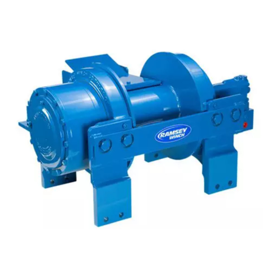
- Page 1 OPERATING, SERVICE AND MAINTENANCE MANUAL MODEL HD-P50,000 INDUSTRIAL PLANETARY WINCH WITH AIR TENSIONER AND 2 SPEED MOTOR CAUTION: READ AND UNDERSTAND THIS MANUAL BEFORE INSTALLATION AND OPERATION OF WINCH. SEE WARNINGS! OM 914244-0414-G...
-
Page 2: Table Of Contents
TABLE OF CONTENTS INTRODUCTION ……………………………… WARRANTY INFORMATION ……………………………… SPECIFICATIONS ……………………………… WARNINGS ……………………………… HYDRAULIC SYSTEM REQUIREME ……………………………… PERFORMANCE CHARTS ……………………………… WINCH OPERATION ……………………………… CLUTCH OPERATION ……………………………… CABLE INSTALLATION ……………………………… MAINTENANCE ……………………………… TROUBLE SHOOTING GUIDE ……………………………… INSTRUCTIONS FOR OVERHAUL ……………………………… 5-9 ……………………………… 10 MOUNTING CONFIGURATIONS DIMENSIONAL DRAWING ………………………………... -
Page 3: Introduction
If the need should arise, warranty procedure is outlined on the back of your self-addressed postage paid warranty card. Please read and fi ll out the enclosed warranty card and send it to Ramsey Winch Company. If you have any problems with our winch, please follow instructions for prompt service on all warranty claims. -
Page 4: Hydraulic System Requireme
HYDRAULIC SYSTEM REQUIREMENTS HYDRAULIC SYSTEM REQUIREMENTS Refer to the performance charts to properly match your hydraulic system to HDP-50000 winch performance. The charts consist of: (1) Line pull (lb.) fi rst layer vs. working pressure (PSI) and (2) Line speed (FPM) fi rst layer vs. fl ow (GPM). Performance is based on a motor displacement of 11.9 cubic inches with 25 GPM maximum fl... -
Page 5: Winch Operation
WINCH OPERATION WINCH OPERATION The best way to get acquainted with how your winch operates is to make test runs before you use it. Plan your test in advance. Remember, you hear your winch, as well as see it operate. Learn to recog- nize the sounds of a light steady pull, a heavy pull, and sounds caused by load jerking or shifting. -
Page 6: Maintenance
MAINTENANCE MAINTENANCE Adhering to the following maintenance schedule will keep your winch in top condition and per- forming as it should with a minimum of repair. A. WEEKLY 1. Check the oil level and maintain it to the oil level plug. If oil is leaking out, determine location and repair. -
Page 7: Instructions For Overhaul
INSTRUCTIONS FOR OVERHAUL DIS-ASSEMBLY 1. Drain oil from gear housing cover by removing pipe plug #37 and relief fi tting #32. Remove tensioner assembly 2. Disconnect tube #40 from elbow #43 on valve #41 and fi tting #29 on brake #30b. Remove motor #33 and gasket #30a by removing (2) capscrews #22. - Page 8 3. Remove (12) capscrews #18 to remove gear housing cover and gasket from ring gear. Remove input thrust washer, sun gear and input carrier assembly from inside ring gear. Remove ring gear and gasket. Remove output carrier assembly. Inspect gear housing cover bushing #15 for damage or wear.
- Page 9 5. Remove clutch housing #27 with piston #28 inside. To remove piston from clutch housing apply air to 1/8” port. Remove o-rings #28 and #35 and inspect for damage or wear. 6. Remove (9) springs #39, thrust washer #26, gasket #31, output shaft #12 and spacer #13 from gear end bearing.
- Page 10 7. Remove winch tie bars #2 and #3 by removing (8) capscrews #19, (8) lock washers # 24, and (4) shoulder bolts #25. Pull gear end bearing #7 from drum assembly #1. 8. Pull drum assembly #1 from end bearing #6. Remove quad-rings #34 from grooves in drum bush- ings.
- Page 11 9. If splines inside drum driver #102 are damaged, drum driver must be replaced. Remove drum driver by unscrewing (8) capscrews #105. If bushings show signs of wear, replace by pressing old bushings from drum #101 and removing o-rings from grooves in drum and drum driver. Place well oiled o-rings #106 into driver and drum.
-
Page 12: Mounting Configurations
WINCH MOUNTING CONFIGURATION... -
Page 13: Dimensional Drawing
DIMENSIONAL VIEWS... -
Page 15: Parts List And Part Drawing
EXPLODED VIEW HDP 50,000... - Page 17 DRUM ASSEMBLY AND PARTS LIST...
- Page 18 CABLE TENSIONER AND PARTS LIST...
-
Page 19: Limited Warranty
If fi eld service at the request of the Buyer is rendered and the fault is found not to be with RAMSEY WINCH’s product, the Buyer shall pay the me and expense to the fi...


Need help?
Do you have a question about the HD-P50000 and is the answer not in the manual?
Questions and answers