Toro Reelmaster 5010-H Operator's Manual
Traction unit
Hide thumbs
Also See for Reelmaster 5010-H:
- Diagnostic manual (476 pages) ,
- Service manual (335 pages) ,
- Operator's manual (128 pages)

Related Manuals for Toro Reelmaster 5010-H


Summary of Contents for Toro Reelmaster 5010-H
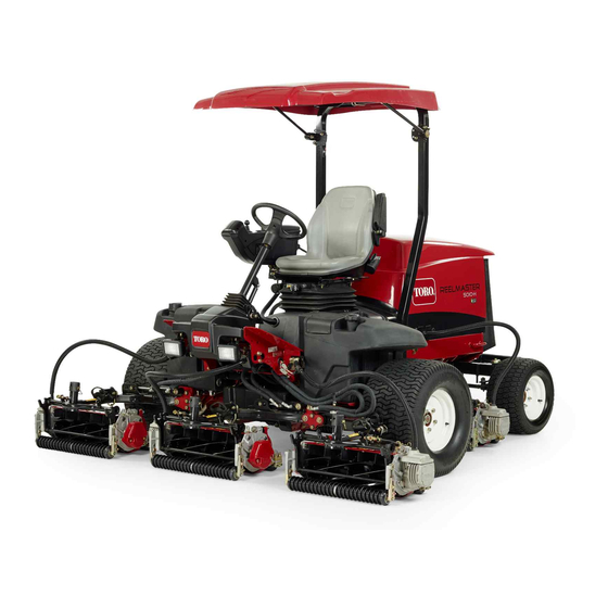
- Page 1 Form No. 3426-959 Rev B Reelmaster ® 5010-H Traction Unit Model No. 03674—Serial No. 403430001 and Up *3426-959* B Register at www.Toro.com. Original Instructions (EN)
- Page 2 It is a violation of California Public Resource Code additional information, contact an Authorized Service Section 4442 or 4443 to use or operate the engine on Dealer or Toro Customer Service and have the model and serial numbers of your product ready. Figure 1...
-
Page 3: Table Of Contents
Contents Servicing the Water Separator ......41 Servicing the Fuel-Pickup Tube ......42 Bleeding Air from the Fuel Injectors....42 Safety ............... 4 Electrical System Maintenance ......43 General Safety........... 4 Electrical System Safety ........43 Safety and Instructional Decals ......4 Servicing the Battery......... -
Page 4: Safety
Safety • Do not operate the machine without all guards and other safety protective devices in place and functioning properly on the machine. This machine has been designed in accordance • Keep children, bystanders, and pets out of the with EN ISO 5395 (when you complete the setup operating area. - Page 5 decalbatterysymbols Battery Symbols decal110-0986 110-0986 Some or all of these symbols are on your battery. 1. Press the brake pedal and parking brake pedal to set the 1. Explosion hazard 6. Keep bystanders away parking brake. from the battery. 2. Press the brake pedal to apply the brake. 2.
- Page 6 decal120-4158 120–4158 1. Read the Operator’s 3. Engine—preheat Manual. 2. Engine—start 4. Engine—stop decal125-8754 125–8754 1. Head lights 6. Slow 2. Engage 7. Lower the cutting units 3. Power take-off (PTO) 8. Raise the cutting units 4. Disengage 9. Read the Operator’s Manual.
- Page 7 decal133-8062 133-8062 decal127-2470 127-2470 decal133-2930 133-2930 1. Warning—do not operate this machine unless you are trained. 4. Tipping hazard—drive slowly when turning; do not turn sharply while traveling fast; only drive on slopes with the cutting units lowered; always wear a seatbelt. 2.
- Page 8 decal133-2931 133-2931 Note: This machine complies with the industry standard stability test in the static lateral and longitudinal tests with the maximum recommended slope indicated on the decal. Review the instructions for operating the machine on slopes in the Operator’s Manual as well as the conditions in which you would operate the machine to determine whether you can operate the machine in the conditions on that day and at that site.
-
Page 9: Setup
Setup Loose Parts Use the chart below to verify that all parts have been shipped. Procedure Description Qty. – No parts required Adjust the tire pressure. – No parts required Adjust the control-arm position. Cutting units Install the cutting units. Mount the finishing kits (finishing kits Finishing kit are sold separately). -
Page 10: Adjusting The Tire Pressure
Adjusting the Tire Pressure No Parts Required Procedure The tires are over-inflated for shipping. Therefore, release some of the air to reduce the pressure. Correct air pressure in the front and rear tires is 83 to 103 kPa (12 to 15 psi). Important: Maintain even pressure in all tires to ensure uniform contact with the turf. - Page 11 Make sure that the counter weight (Figure 4) is Mount the spring-tube bolt to the opposite installed to the proper end of the cutting unit as tab on the carrier frame and secure with the described in the counter weight kit Installation flange nut.
- Page 12 Note: Use the number of chain links described in the cutting unit Operator's Manual. g003948 Figure 10 3. Pin 1. Lift-arm chain 2. Chain bracket g003977 Figure 8 1. Lift arm 3. Lift-arm-pivot yoke Coat the spline shaft of the reel motor with clean grease.
-
Page 13: Mounting The Finishing Kits
Note: When tightening the nuts, use a back up wrench to prevent the hose from twisting or kinking. Insert the connector plate onto the bulkhead-mounting bolts with the connectors positioned as shown in Figure Secure the connector plate to 1 of the mounting bolts with the flange nut previously removed. - Page 14 g032153 Figure 15 No. 3 Cutting Unit Location, Right Rear g027129 Figure 13 No. 1 Cutting Unit Location, Center Front 1. Extra flange nut 3. Connector plate (As viewed from under the machine) 2. Bulkhead bracket 3. Bulkhead bracket 1. Connector plate 2.
-
Page 15: Adjusting The Turf-Compensation Spring
Adjusting the Installing the CE Hood Turf-Compensation Spring Latch Parts needed for this procedure: No Parts Required Hood-latch assembly Procedure Washer The turf-compensation spring (Figure 17) transfers Procedure the weight from the front to the rear roller. This helps to reduce a wave pattern in the turf, also known as Unlatch and raise the hood. -
Page 16: Using The Cutting-Unit Kickstand
Outside the hood, insert the hook end of the latch through the hole in the hood. Make sure that the rubber sealing washer remains on the outside of the hood. Inside the hood, insert the metal washer onto the latch and secure with the nut. Make sure that the latch engages the frame catch when it is locked. -
Page 17: Product Overview
Traction Pedal Product Overview The traction pedal (Figure 24) controls the forward and reverse operation. Press the top of the pedal to move forward and the bottom to move rearward. The ground speed depends on how far you press the pedal. For no load, maximum ground speed, fully press the pedal while the throttle is in the F position. - Page 18 Key Switch The key switch (Figure 25) has 3 positions: O , and S REHEAT TART Lower Mow/Raise Control Lever This lever (Figure 25) raises and lowers the cutting units and also starts and stops the cutting units when the cutting units are enabled in the M mode.
- Page 19 g020650 Figure 28 1. Indicator light 3. Middle button 2. Right button 4. Left button • Left Button, Menu Access/Back Button— Press this button to access the InfoCenter menus. You can use it to back out of any menu you are currently using.
- Page 20 InfoCenter Icon Description InfoCenter Icon Description (cont'd.) SERVICE DUE Indicates when scheduled service should be performed Battery Hour meter Motor/Generator (not charging) Info icon Motor/Generator (charging) Fast E-Reel Slow Front Backlap Rear Backlap Fuel level The cutting units are lowering. The cutting units are raising.
- Page 21 The Faults menu contains a list InfoCenter. The menu choices of the recent machine faults. are English or Metric. Refer to the Service Manual or contact your Toro Distributor Language Controls the language used on the InfoCenter*. for more information on...
- Page 22 Press the middle button to enter the code. About If the code has been accepted and the protected Menu Item Description menu has been unlocked, “PIN” is be displayed Model Lists the model number of the in the upper right corner of the display screen. machine.
- Page 23 Setting the Front and Rear Reel Speeds Although the front and rear reel speeds are calculated by inputting the number of blades, mow speed and HOC into the InfoCenter, the setting can be manually changed to accommodate for different mowing conditions.
-
Page 24: Specifications
Contact your Authorized Service Dealer or authorized Toro Before Operation distributor or go to www.Toro.com for a list of all approved attachments and accessories. To ensure optimum performance and continued safety Before Operation Safety certification of the machine, use only genuine Toro replacement parts and accessories. -
Page 25: Performing Daily Maintenance
• • Extinguish all cigarettes, cigars, pipes, and other The biodiesel portion of the fuel must meet sources of ignition. specification ASTM D6751 or EN14214. • • Use only an approved fuel container. The blended fuel composition should meet ASTM D975 or EN590. -
Page 26: Bleeding The Fuel System
for 15 seconds. Proceed backward at full reverse speed and ride the brake for 15 seconds. Repeat this 5 times waiting 1 minute between each forward and reverse cycle to avoid overheating the brakes. An adjustment to the brakes may be required after break-in;... - Page 27 • causes distractions; otherwise, injury or property Keep the ROPS in safe operating condition by damage may occur. thoroughly inspecting it periodically for damage and keeping all the mounting fasteners tight. • Before you start the engine, ensure that all drives are in neutral, the parking brake is engaged, and •...
-
Page 28: Starting The Engine
Starting the Engine Important: You must bleed the fuel system before starting the engine if you are starting the engine for the first time, the engine has shut off due to lack of fuel, or you have performed maintenance on the fuel system; refer to Bleeding the Fuel System (page 26). -
Page 29: Setting The Reel Speed
Setting the Reel Speed To achieve a consistent, high quality-of-cut and a uniform after cut appearance, it is important that you set the reel speed to the proper setting. Adjust the reel speed as follows: In the InfoCenter, under the settings menu, enter the blade count, mow speed, and HOC to calculate the proper reel speed. -
Page 30: Adjusting The Lift-Arm Counterbalance
Adjusting the Lift-Arm turnaround height or move the switch up to decrease the lift-arm turnaround height (Figure Counterbalance 34). You can adjust the counterbalance on the rear cutting-unit lift arms to compensate for different turf conditions and to maintain a uniform height of cut in the rough conditions or in areas of thatch buildup. -
Page 31: Checking The Interlock Switches
Checking the Interlock Verifying the Output Function Park the machine on a level surface, lower the Switches cutting units, shut off the engine, engage the parking brake, and remove the key. The purpose of the interlock switches is to prevent the engine from cranking or starting unless the traction Turn the key to the O position and start the... -
Page 32: After Operation
position. Move the Mow/Transport lever to the position. Be careful when driving between RANSPORT objects so you do not accidentally damage the machine or cutting units. Use extra care when operating the machine on slopes. Drive slowly and avoid sharp turns on slopes to prevent rollovers. Lower the cutting units when going downhill for steering control. -
Page 33: Hauling The Machine
g003995 Figure 39 1. Bypass-valve bolt g031850 Figure 38 Close the bypass valve before starting the 1. Front jacking point engine. However, do not exceed 7 to 11 N∙m (5 to 8 ft-lb) torque to close the valve. • Rear—rectangular axle tube on the rear axle. Important: Running the engine with the bypass valve open causes the transmission... -
Page 34: Maintenance
• To ensure safe, optimal performance of the – Shut off the engine and remove the key. machine, use only genuine Toro replacement – Wait for all moving parts to stop. parts. Replacement parts made by other – Allow machine components to cool before manufacturers could be dangerous, and such use performing maintenance. - Page 35 Maintenance Service Maintenance Procedure Interval • Service the air cleaner. Service the air cleaner earlier if the service indicator shows red. Service it more frequently in extremely dirty or dusty conditions. • Check the fuel lines and connections for deterioration, damage, or loose Every 400 hours connections.
-
Page 36: Daily Maintenance Checklist
Daily Maintenance Checklist Duplicate this page for routine use. Maintenance For the week of: Check Item Mon. Tues. Wed. Thurs. Fri. Sat. Sun. Check the safety interlock operation. Check the brake operation. Check the levels of the engine oil and fuel. Check the cooling-system fluid level. -
Page 37: Lubrication
Important: Refer to your engine owner’s manual and cutting unit Operator's Manual for additional maintenance procedures. Note: To obtain an electrical schematic or a hydraulic schematic for your machine, visit www.Toro.com. Lubrication Greasing the Bearings and Bushings Service Interval: Every 50 hours (and immediately... - Page 38 g004157 Figure 43 • Rear axle tie rod (2) (Figure g003966 Figure 46 • Brake pedal (1) (Figure g011615 Figure 47 g003987 Figure 44 • Axle-steering pivot (1) (Figure g004169 Figure 45 • Steering-cylinder ball joints (2) (Figure...
-
Page 39: Engine Maintenance
Engine Maintenance remove large accumulations of debris packed between outside of the filter and the canister. Important: Avoid using high-pressure air, Engine Safety which could force dirt through the filter into the intake tract. • Shut off the engine before checking the oil or adding oil to the crankcase. -
Page 40: Checking The Engine-Oil Level
Preferred oil: SAE 15W-40 (above 0°F) • Alternate oil: SAE 10W-30 or 5W-30 (all temperatures) Toro Premium Engine oil is available from your distributor in either 15W-40 or 10W-30 viscosity. g004134 Figure 51 Park the machine on a level surface, lower the cutting units, shut off the engine, and remove 1. -
Page 41: Fuel System Maintenance
Fuel System Maintenance DANGER Under certain conditions, fuel and fuel vapors are highly flammable and explosive. A fire or explosion from fuel can burn you and others and can cause property damage. • Fill the fuel tank outdoors, in an open area, when the engine is off and is cold. -
Page 42: Servicing The Fuel-Pickup Tube
Bleeding Air from the Fuel Injectors Note: Perform this procedure only if the fuel system has been purged of air through normal priming procedures and the engine does not start; refer to Bleeding the Fuel System (page 26). Loosen the pipe connection to the No. 1 nozzle and holder assembly (Figure 55). -
Page 43: Electrical System Maintenance
Replacing the Fuses Electrical System Maintenance There are 8 fuses in the 12 V electrical system. The fuse block (Figure 56) is located behind the control-arm-access panel. Important: Before welding on the machine, disconnect all cables from the battery, both wire harness plugs from the electronic control module, and the terminal connector from the alternator to prevent damage to the electrical system. - Page 44 decal127-2470 Figure 60 g027135 Figure 58 1. Fuse-block cover 2. Fuse block g027136 Figure 59 1. Fuse...
-
Page 45: Drive System Maintenance
Drive System Maintenance Checking the Tire Pressure Service Interval: Before each use or daily Check the tire pressure. The correct air pressure in the front and rear tires is 83 to 103 kPa (12 to 15 psi). DANGER Low tire pressure decreases machine side hill stability. -
Page 46: Cooling System Maintenance
Cooling System Maintenance Cooling System Safety • Swallowing engine coolant can cause poisoning; keep out of reach from children and pets. • Discharge of hot, pressurized coolant or touching a hot radiator and surrounding parts can cause severe burns. – Always allow the engine to cool at least 15 minutes before removing the radiator cap. -
Page 47: Removing Debris From The Cooling System
g003951 g004138 Figure 63 Figure 64 1. Expansion tank 1. Rear-screen latch 2. Rear screen Clean the screen thoroughly with compressed If the coolant level is low, remove the expansion air. tank cap and replenish the system. Do not overfill. Pivot the latches inward to release the oil cooler (Figure 65). -
Page 48: Brake Maintenance
Brake Maintenance Adjusting the Parking Brakes Adjust the brakes when there is more than 25 cm (1 inch) of free travel (Figure 67) of the brake pedal, or when more holding force is required. Free travel is the distance that the brake pedal moves before you feel braking resistance. -
Page 49: Adjusting The Parking-Brake Latch
Belt Maintenance Note: Ensure that the cable conduit does not rotate while you are tightening the nuts. Tensioning the Alternator Adjusting the Belt Parking-Brake Latch Service Interval: After the first 8 hours If the parking brake fails to engage and latch, an Every 100 hours adjustment to the brake pawl is required. -
Page 50: Hydraulic System Maintenance
(Figure 71). changes. Alternative hydraulic fluids: If Toro PX Extended Life Hydraulic Fluid is not available, you may use another conventional, petroleum-based hydraulic fluid having specifications that fall within the listed range for all the following material properties and that it meets industry standards. -
Page 51: Hydraulic Fluid Capacity
This fluid is compatible with the elastomers used Disconnect the hose from the bottom of the in Toro hydraulic systems and is suitable for a fitting and let the hydraulic fluid flow into the wide-range of temperature conditions. This fluid is drain pan. -
Page 52: Replacing The Hydraulic Filter
Hydraulic System Service Interval: Every 1,000 hours—If you Use the hydraulic system test ports to test the are using the recommended pressure in the hydraulic circuits. Contact your Toro hydraulic fluid, replace the Distributor for assistance. hydraulic filters. Use the test ports on the front hydraulic tubes (Figure Every 800 hours—If you are not using the... -
Page 53: Cutting Unit System Maintenance
Cutting Unit System Use the test port on the hydraulic tube (Figure 75) to assist in troubleshooting the charge-pressure circuit. Maintenance Blade Safety • A worn or damaged blade or bedknife can break, and a piece could be thrown toward you or bystanders, resulting in serious personal injury or death. -
Page 54: Storage
After completing Coat the cable terminals and battery posts adjustments, repeat steps through . with Grafo 112X skin-over grease (Toro Part Repeat the procedure for all cutting units you No. 505-47) or petroleum jelly to prevent want to backlap. - Page 55 Shut off the engine and remove the key. Flush the fuel tank with fresh, clean fuel. Secure all of the fuel-system fittings. Thoroughly clean and service the air-cleaner assembly. Seal the air-cleaner inlet and the exhaust outlet with weatherproof tape. Check the antifreeze protection and add a 50/50 solution of water and ethylene glycol antifreeze as needed for the expected minimum...
- Page 56 Notes:...
- Page 57 Notes:...
- Page 58 The Toro Company (“Toro”) respects your privacy. When you purchase our products, we may collect certain personal information about you, either directly from you or through your local Toro company or dealer. Toro uses this information to fulfil contractual obligations - such as to register your warranty, process your warranty claim or to contact you in the event of a product recall - and for legitimate business purposes - such as to gauge customer satisfaction, improve our products or provide you with product information which may be of interest.
- Page 59 While the exposure from Toro products may be negligible or well within the “no significant risk” range, out of an abundance of caution, Toro has elected to provide the Prop 65 warnings. Moreover, if Toro does not provide these warnings, it could be sued by the State of California or by private parties seeking to enforce Prop 65 and subject to substantial penalties.
- Page 60 Countries Other than the United States or Canada Customers who have purchased Toro products exported from the United States or Canada should contact their Toro Distributor (Dealer) to obtain guarantee policies for your country, province, or state. If for any reason you are dissatisfied with your Distributor's service or have difficulty obtaining guarantee information, contact your Authorized Toro Service Center.
Need help?
Do you have a question about the Reelmaster 5010-H and is the answer not in the manual?
Questions and answers