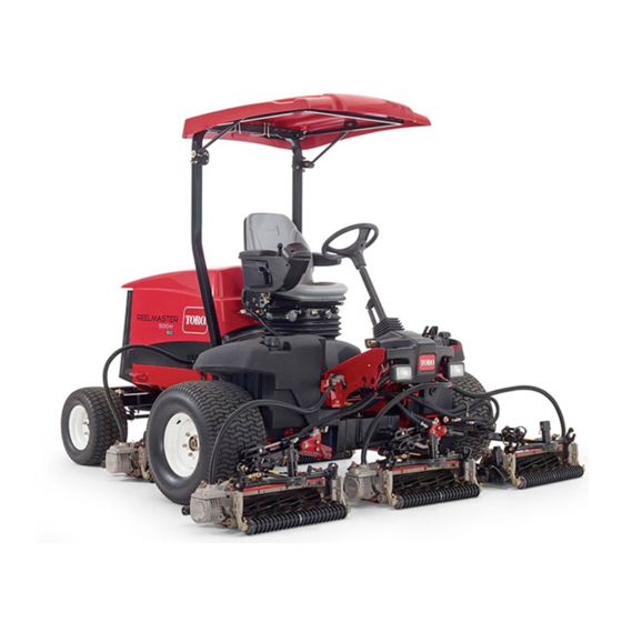
Toro Reelmaster 5010-H Series Installation Instructions Manual
Rear roller brush kit, cutting unit with 5in or 7in reel
Hide thumbs
Also See for Reelmaster 5010-H Series:
- Diagnostic manual (1180 pages) ,
- Service manual (335 pages) ,
- Operator's manual (128 pages)
Advertisement
Quick Links
Rear Roller Brush Kit
Reelmaster
Model No. 03406
Model No. 03408
This product complies with all relevant European directives. For details, please see the Declaration of
Incorporation (DOI) at the back of this publication.
The rear roller brush kit is mounted to the reel mowers on a ride-on machine and is intended to be used by
professional, hired operators in commercial applications. It is primarily designed to keep the rear roller of the
cutting unit free of grass and debris, which leads to a better after-cut appearance on well-maintained lawns in
parks, sports fields, and on commercial grounds.
Installation
Loose Parts
Use the chart below to verify that all parts have been shipped.
Description
No parts required
Roller-brush housing
Hex-socket bolt, 3/8 x 1 inch
Roller-brush assembly
Shoulder bolt
Right belt cover/plate assembly
Left belt cover/plate assembly
Bolt (5/16 x 1/2 inch)
Spacer
Drive pulley
Flange-head bolt (3/8 x 2 inches)
Belt
Shim washer (as required for belt alignment)
Right driveshaft
Left driveshaft
High height-of-cut brush (optional)
End weight kit (Model 03413) for the
Reelmaster 5010-H with 5-inch cutting unit
Note:
Determine the left and right sides of the cutting
unit from behind the cutting unit.
Important:
Use the Rear Roller Brush Kit only
when cutting in the height-of-cut range of 6 to
25 mm (1/4 to 1 inch). Use the high height-of-cut
brush when cutting above 25 mm (1 inch). Refer to
the procedure for Installing the High Height-of-Cut
Brush (Optional).
© 2019—The Toro® Company
8111 Lyndale Avenue South
Bloomington, MN 55420
®
5010-H Series Cutting Unit with 5in or 7in Reel
Qty.
–
Determine the roller brush orientation.
5
10
5
5
2
3
20
Install the roller brush.
5
5
5
5
5
2
3
Install the high height-of-cut brush—for HOC greater than
—
2.5 cm (1 inch).
Install the end weight kit for the Reelmaster 5010-H with
—
5-inch cutting units.
Note:
motors need the additional end-weight kit (Model
03413).
Register at www.Toro.com.
Form No. 3397-977 Rev C
Installation Instructions
Use
5-inch cutting units driven by electric reel
Original Instructions (EN)
All Rights Reserved *3397-977* C
Printed in the USA
Advertisement

Related Manuals for Toro Reelmaster 5010-H Series


Summary of Contents for Toro Reelmaster 5010-H Series
- Page 1 25 mm (1/4 to 1 inch). Use the high height-of-cut brush when cutting above 25 mm (1 inch). Refer to the procedure for Installing the High Height-of-Cut Brush (Optional). © 2019—The Toro® Company Register at www.Toro.com. Original Instructions (EN) All Rights Reserved *3397-977* C...
- Page 2 Determining the Roller Installing the Roller Brush Brush Orientation Installing the Driveshaft All cutting units are shipped with the counterweight Park the machine on a level surface and set the mounted to the left end of the cutting unit. Refer to parking brake.
- Page 3 Mounting the Roller-Brush housing with 2 bolts (5/16-18 x 1 1/2 inches); refer to Figure Housing Ensure that the O-ring is installed on the roller-brush housing (Figure g020371 Figure 3 g028040 Figure 5 1. Roller-brush housing 2. O-ring 3. Roller-brush housing 1.
- Page 4 roller-brush mounting brackets and the side-plate mounting flanges. Save the additional 6 mm (1/4 inch) spacers for potential later use. Secure the brush-assembly mounting brackets to the cutting-unit side plates with the nuts previously removed. Installing the Roller Brush Plate Slide each excluder seal outward until the lip seals are in light contact with each bearing housing...
- Page 5 Note: The shoulder bolt should not clamp the plate to the housing. Check to ensure that the roller-brush plate is parallel to the cutting-unit side plate. If it is not parallel, proceed as follows: Loosen the 2 flange locknuts securing the roller-brush mounting bracket to the cutting-unit side plate (Figure...
-
Page 6: Installing The Belt
Important: If the bolt is not properly torqued, the bolt will come loose. g027195 Figure 13 1. Driveshaft 3. Drive pulley 2. Spacer 4. Flange-head bolt—torque to 47 to 54 N·m (35 to 40 ft-lb) g027303 Figure 12 Installing the Belt 1. -
Page 7: Completing The Installation
g027197 Figure 16 Slide the belt cover onto the mounting bolts and secure the cover with 2 flange nuts (Figure 17). Important: Do not overtighten the nuts as damage to the cover may occur. g020390 Figure 15 1. Belt 2. 9/16-inch deep-well socket Important: Ensure that the ribs on the belt are properly seated in the grooves in each... - Page 8 Installing the High Clamp the brush onto the shaft with the 2 J-bolts and nuts previously removed (Figure 21). Height-of-Cut Brush Important: Insert the threaded end of the J-bolts through the outer holes of the brush (Optional) shaft while hooking the curved ends of the J-bolts into the inner holes.
-
Page 9: Maintenance
Maintenance If the pulley needs to move out, add a 0.8 mm (0.032 inch) thick washer (Figure 23). • Ensure that the brush is parallel to the roller with Note: If the pulley needs to move in, remove 1.5 mm (0.060 inch) clearance to light contact. the existing 0.8 mm (0.032 inch) thick washer. - Page 10 Place the pry bar against the weld side of the reel support plate (Figure 26). Note: Insert the pry bar between the top of the reel shaft and the backs of 2 reel blades so that the reel will not move. Important: Do not contact the cutting edge of any blades with the pry bar;...
- Page 11 Restraining the Reel for Installing Threaded Inserts Insert a long-handled pry bar (recommended 3/8" x 12" with screwdriver handle) through the front of the cutting reel, closest to the side of the cutting unit that you will be torquing (Figure 27).
- Page 12 The method of transmission shall be electronic transmittal. This machinery shall not be put into service until incorporated into approved Toro models as indicated on the associated Declaration of Conformity and in accordance with all instructions, whereby it can be declared in conformity with all relevant Directives.
Need help?
Do you have a question about the Reelmaster 5010-H Series and is the answer not in the manual?
Questions and answers