Table of Contents
Advertisement
Advertisement
Table of Contents

Related Manuals for Samsung VMR-I HD Series


Summary of Contents for Samsung VMR-I HD Series
-
Page 1: Catologue
VMR-I Product Manual 1 / 56... -
Page 2: Table Of Contents
Catologue Catologue ........................1 1.1 VMR-I HD Series Product Introduction ..........3 Chapter 2 Safety......................5 Safety Guidelines ................5 2.2 Safety Statement .................. 6 2.3 Warning Statement ................6 2.4 Instructions for Use ................7 3.1 Structure Requirements ............... 8 3.2 Electrical Requirement ................. -
Page 3: Vmr-I Hd Series Product Introduction
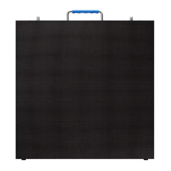
Dear users, you are welcome to use Samsung products. We are very pleased if this manual is helpful for you. This manual is intended to provide you with an installation instruction. If you encounter any problems during usage, or if you have any suggestions, please contact us according to the contact information in the manual, We will try our best to solve this problem. - Page 4 1.2 Product Outlook 4 / 56...
-
Page 5: Chapter 2 Safety
Before installing the VMR-I Series enclosure, please ensure that you understand and follow the safety guidelines, safety instructions and warnings in this section. In this manual, the “VMR-I HD Series” contains the following products from the company: ... -
Page 6: Safety Statement
Moisture-proof: The maximum relative humidity of the work should be less than Waterproof: The VMR-I HD series is an indoor product. It is absolutely forbidden to use it in an outdoor environment, and it is not allowed to pour liquid into the inside or outside of the cabinet or the display. -
Page 7: Instructions For Use
VMR-I HD Series modules should not be used near any device other than CE and UL / ETL certified. The VMR-I HD series is an indoor product. Do not install or use it in an outdoor environment. Keep the product in a dry environment and avoid direct sunlight. ... -
Page 8: Structure Requirements
The same safety coefficient shall be applied to other lifting devices. Note: Each VMR-I HD series cabinet weighs less than 8.0kg per cabinet,, 32 kg per square meter. ... -
Page 9: Chapter 4 Displaying System
Chapter 4 Displaying System This chapter mainly introduces the displaying system connection diagram of the VMR-I HD series products, and introduces the main accessories of display screen. 4.1 Displaying System Connection Diagram 1. Sending box---send video data to the display;... -
Page 10: Cabinet And Cabling
5.1 Cabinet and Cabling Parts on the cabinet and the cabinet: As shown in Picture 5-1, the VMR-I HD series cabinet consists of four modules. The cabinet size is 500*500mm, and the size of each module is 250. - Page 11 lock the adjacent cabinets for flat or curve connection; 6. Test button: used during testing; 7. Safety lock----protect the power box; 8. Module----Product display module; 9. Locking lever on the cabinet----Locking the cabinet. 10. Safety rope----Hang the module and protect the module. 11.
-
Page 12: Mounting Accessories
Picture 5-3 Main signal cable Cabinet power cable: Connect the power supply box between the cabinet and the cabinet. The cable size is 3*2.5mm2, as shown in Picture 5-4. Picture 5-4 Cabinet Power Line Cabinet signal cable: Connects the signal between the cabinet and the cabinet, and exceeds the five types of network cables, as shown in Picture 5-5. - Page 13 Picture 5-6 Hanging Bar ① Hold the truss ② Lock the locking bars of the two adjacent cabinets. 5.2.2 Floor stacking bracket: The stacking frame used for stacking can be freely connected to form a large frame to meet the installation requirements, as shown in Picture 5-7. Picture 5-7 Foldable Bracket 13 / 56...
-
Page 14: Power Distribution Cabinet
Picture 5-9 Power Distribution Cabinet Remarks: Samsung Company provides customers with standard power distribution cabinets with 8, 12, and 16 interfaces. It can also customize special power distribution cabinets for customers, such as power distribution cabinets with remote power-on functions and more interfaces. - Page 15 Picture 5-10 Front & Rear View Receiving card: Receive and process the data transmitted by the sending box, so that the video is perfectly displayed on the display. The receiving card complies with the EU RoHS and CE-EMC standards, as shown in Picture 5-11. Picture 5-11 Receiver Card ...
- Page 16 Picture 5-12 NovaLCT-Mars Control System Interface Video processor: processing various video signals, converting DVI, HDMI, AV, VGA and other signals into DVI signals, improving picture quality, providing a better picture for the display, as shown in Picture 5-13. (Different items will choose different types of video processors, the appearance and function will be different) Picture 5-13 Video Processor ...
-
Page 17: Other Accessories
5.5 Other Accessories Vacuum tool: When using the module, take the module and remove the module from the cabinet to achieve pre-maintenance. For details, see Appendix D - How to use the air suction tool. Picture 5-15 Vacuum Tool ... -
Page 18: Place Installation
Picture 5-17 Flight Case Chapter 6 VMR-I Installation Process This chapter mainly introduces the installation process of the VMR-I HD series products and guides the customer to install the products correctly. The VMR-I HD series products generally adopt two installation methods: stacking and hangig, which are described in detail in this chapter. - Page 19 Step 1: Install the base beam. The base beam is the first layer of a screen to ensure flatness. The base beam can be spliced into the length as requeste by installation requirements, as shown in Picture 6-1. Picture 6-1 Stacking Base Beam Step 2: Install the standing base bar.
- Page 20 Picture 6-3 Supporting Frame Step 4: Install the maintenance access board. Fix the maintenance access board on the bracket as shown below, which is convenient for maintenance, as shown in Picture 6-4. Picture 6-4 Maintenance Access Board Step 5: Install the bracket connector. The height of the connector is determined by the height of the cabinet, as shown in Picture 6-5.
-
Page 21: Cabinet Installation
Picture 6-5 Bracket Connector 6.1.3 Cabinet Installation 1. First, wear anti-static gloves and operate with more than one person. 2. Take off the cabinet from the flightcase in a slowly and gentle way, and unwrap the PE package and press the automatic protection angle. [If the cabinet is not equipped with the automatic corner guard, the sheet metal corner can be removed with a screwdriver] And place the cabinet completely on the ground or on the desktop, as shown in Picture 6-6, 6-7. - Page 22 Picture 6-6Take out cabinet Picture 6-7 Press to unfold the automatic connection corner Start installing the cabinet. After ensuring that the base beam is flat, gently place and lock each cabinet. Each time a cabinet is erected, a cabinet is lit immediately to check if any dead lights, obvious bright lines, and flatness.
-
Page 23: Attention Notes
6.2 Hanging In the case of installation locations changing frequently, hanging is usually used, which is common in the rental market. For the VMR-I HD Series, Samsung provides customers with a truss and FlyKit for quick haing installation. The following are detailed steps. - Page 24 Picture 6-11 Truss Install the FLYKIT and install the FLYKIT according to the position of the upper and lower locking bars of the cabinet, as shown in Picture 6-12. Picture 6-12 Hanging Bra Installation 3. Cabinet Installation Picture 6-13 Cabinet Installation 1.
- Page 25 2. The single unit of the cabinet is carefully taken out from the flightcase, and the PE tape and the protection angle are removed in turn. [If the cabinet is not equipped with the automatic corner guard, the side of the sheet metal corner needs to be removed with a screwdriver to remove the corner guard.] Place it on the ground or on the table, as shown in Pictures 6-14, 6-15.
- Page 26 Chapter 7 VMR-I Cable Connection This chapter describes how the signal and power cables of the VMR-I HD Series are connected. 7.1 VMR-I HD series product cabinet interface introduction Picture 7-1 VMR-I Cabinet Connection Port ① Power Output ② Power Input ③...
-
Page 27: Power Distribution Cabinet
The maximum current of the aviation head used in the VMR-I HD series cabinet is 20A. To avoid the safety problems such as overheating and fire, the total current of the cabinets cascaded by one main power supply must be <20*0.8. -
Page 28: Sending Box
②Main power cord ③Power cascade Picture 7-2 Power cable connection diagram 7.3 Signal cable connection 7.3.1 Sending box: The sending box contains a sending card to send video data to the display. 7.3.2 Main Power Cord: Send the main signal cable between the cabinet and the display screen to transmit video data with a length of less than 70m. - Page 29 3. After the cabinet is installed, connect the signal wires according to the design drawings. Picture 7-3 shows the signal cable connection of the VMR-I P2.6 10*6 arrangement. Each main network cable carries 192*192*15=552960 pixels. ① Sending box ② Main signal cable ③...
-
Page 30: Load Display Profile
Chapter 8 VMR-I Displaying Set-up Steps This chapter mainly introduces the setup steps of the VMR-I series product control software. 8.1 NovaLct-Mars Control System Instruction 8.1.1 Load display profile Double-click to open the NovaLCT-Mars software, as shown in Picture 8-10, click “User”—“Advanced Login”... - Page 31 Click the “load files” button on the Scan Board interface, load the “*.RCFG” file corresponding to the display, and then click the “Send to HW” button. After the display shows normal, click “Save”, as shown in Picture 8-12. Picture 8-13. Picture 8-12 31 / 56...
-
Page 32: Screen Connection File Loading
Picture 8-13 Picture 8-14 Note: Do not modify any parameters after the non-professionals load the "*.RFCG" file. If the parameters are inadvertently modified, the display screen will not display properly. The configuration file needs to be reloaded and sent to the receiving card. After sending and saving the configuration file, the display should display the same content in units of the cabinet. - Page 33 Picture 8-15 Picture 8-16 Note: Do not modify any parameters after non-professionals load the "*.Scr" file. If the parameters are inadvertently modified, the display screen is not displayed properly. The screen file needs to be reloaded and sent to the receiving card. At this point, the entire screen connection parameter setting has been completed.
-
Page 34: Appendix A Dimensional Drawing Of Main Components
Appendix A Dimensional Drawing of Main Components A.1 VMR-I HD series cabinet size chart VMR-I P2.6 VMR-I P2.9 34 / 56... - Page 35 VMR-I P3.9 A.2 Flykit 35 / 56...
- Page 36 Appendix B VMR-I Specification Table Product Name VMR-I P 2.6 VMR-I P 2.9 VMR-I P 3.9 Physical Pitch 2.6 mm 2.9 mm 3.9 mm LED Vendor Nationstar Nationstar Nationstar LED Package Name FM2020RGBA-HG FM2020RGBA-HG FM2020RGBA-HG 5nm, G:3nm, 5nm, G:3nm, Size of LED color bin combination R: 5nm, G:3nm, B:3nm B:3nm B:3nm...
- Page 37 Packaging Weight 30 ±1 kg/pcs 30 ±1 kg/pcs 30 ±1 kg/pcs ≥1000nits ≥1000nits ≥1000nits Brightness (after Cal.) Refresh Rate 3,840 Hz 3,840 Hz 3,840 Hz Horizontal Viewing Angle 160° 160° 160° Vertical Viewing Angle 140° 140° 140° Color temperature Optical/ Video - Default 12000K±1500K...
- Page 38 Driver IC Power cable between cabinets Left and right signal cables between cabinets Upper and lower signal cables between cabinets Main power cord Main signal cable Connection piece and screw between cabinets Power aviation head Signal aviation head 38 / 56...
- Page 39 Appendix C Tools to be prepared C.1 Adjustable Wrench (conventional) C.2 Screwdriver (medium size) C.3 Cutting pliers (conventional) 39 / 56...
- Page 40 C.4 Allen key (M3 is used to open the power cabinet, M8 is used to fix the connecting piece) C.5 Plastic hammer 40 / 56...
- Page 41 Appendix D How to use the air suction tool 1 Attach the air suction tool to the surface of the module to be removed, and press it slightly on the surface of the module so that the suction cup of the suction tool fits evenly with the module surface, as shown in the following Picture: Press and hold the air suction tool switch for 3~5 seconds, and the air suction tool sucks the module;...
- Page 42 After removing the module, release the air suction tool switch and the module is successfully removed, as shown below: Remarks: The VMR-I HD series is a small-pitch product that is very easy to damage. All the actions need to be handled gently during the process of disassembling the module.
- Page 43 Appendix E How to use the upper and lower lock levers E.1.2 Push the lock lever up as shown below: E.1.3 The lock lever is pushed up into position and the lock bar lock lever is as shown below: 43 / 56...
- Page 44 E.1.4 Move the handle to the inside according to the arrow of the cabinet, so that the handle is pressed against the cabinet, as shown below: E.1.5 Locking status as shown below E.1.6 Locate the left and right locks and unlock them. Turn the lock lever handle according to the UNLOCK direction of the cabinet to the point where it cannot be rotated.
- Page 45 E.2.1 Initial state: When the cabinet is installed, the position of the upper right lock lever is as shown below. E.2.2 Push the lock lever up as shown below: E.2.3 The lock lever is pushed up into position and the lock bar lock lever is as shown below: 45 / 56...
- Page 46 E.2.4 Move the handle to the inside of the cabinet arrow to press the handle to the cabinet, as shown below: E.2.5 The locking state is as follows: 46 / 56...
- Page 47 E.2.6 Locate the left and right locks and unlock them. Turn the lock lever handle according to the UNLOCK direction of the cabinet to the point where it cannot be rotated. Then push the lock piece pointed by the arrow to unlock it, as shown below: Appendix F How to use the left and right angle locks Initial state: The initial state of the angle lock is as shown in the Picture below.
- Page 48 F2: After the angle lock is adjusted to the required scale, press the handle to press the handle and lock the angle to the desired angle, as shown below: F3:Align the left and right cabinets together, as shown below; Push the lock lever to the left as shown below: 48 / 56...
- Page 49 F5: Turn the lock lever 90° clockwise as shown below: F6: The position of the lock lever is as shown below, as shown below: 49 / 56...
- Page 50 Turn the lock lever handle according to the mark on the cabinet, as shown below: Press the lock handle according to the mark to lock the cabinet, as shown below: 50 / 56...
- Page 51 Appendix G How to Take off the power cabinet Use the M3 Allen key to turn the fuse button in the direction of the mark, as shown below: Press the four buckles shown below and open them as shown below: G3:Hold both ends of the power cabinet with both hands and pull the power cabinet backwards, as shown below: 51 / 56...
- Page 52 G4:Open the back cover of the power supply cabinet as shown below, as shown below: 52 / 56...
- Page 53 Appendix H common troubleshooting methods A. The screen does not light or keeps flashing 1. Check if the power supply is powered. As shown in Picture 1 below: Picture 1 2. Check the DVI line and check if the network cable is in good contact. As shown in Picture 2 below 3.
- Page 54 Picture 3 B. Module Failure: 1. The single lamp does not illuminate, and the LED itself is damaged, resulting in a dead light. As shown in Picture 4: Picture 4 2. A string of lights is not lit or constantly lit, and one of the 16-bit pins of the constant current IC is damaged or soldered.
- Page 55 3. If the IC is not illuminated, the IC may be damaged or the current resistance may be damaged. As shown in Picture 6: Picture 6 4. If a module is not lit, the socket of the module may be loose and cannot be powered. (As shown in Picture 7) cture 7 If one or several lines of the module are not lit, the tube may be damaged.
- Page 56 Picture 1 56 / 56...
Need help?
Do you have a question about the VMR-I HD Series and is the answer not in the manual?
Questions and answers