Graco LineLazer IV 3900 Important Safety Instructions Manual
Airless line stripers
Hide thumbs
Also See for LineLazer IV 3900:
- Operation (54 pages) ,
- Repair and parts manual (38 pages) ,
- Repair parts list manual (38 pages)
Table of Contents
Advertisement
Quick Links
Operation
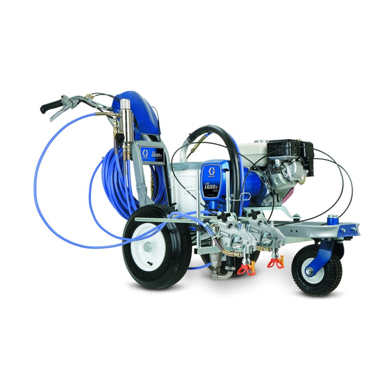
LineLazer
Airless Line Stripers
- For the application of line striping materials -
3300 psi (22.8 MPa, 228 bar) Maximum Working Pressure
Important Safety Instructions
Read all warnings and instructions in this
manual. Save these instructions.
Graco Inc. P.O. Box 1441 Minneapolis, MN 55440-1441
Copyright 2005, Graco Inc. is registered to I.S. EN ISO 9001
™
IV 3900, 5900
311017A
Advertisement
Table of Contents

Related Manuals for Graco LineLazer IV 3900


Summary of Contents for Graco LineLazer IV 3900
- Page 1 3300 psi (22.8 MPa, 228 bar) Maximum Working Pressure Important Safety Instructions Read all warnings and instructions in this manual. Save these instructions. Graco Inc. P.O. Box 1441 Minneapolis, MN 55440-1441 Copyright 2005, Graco Inc. is registered to I.S. EN ISO 9001...
-
Page 2: Table Of Contents
Contents Warnings ........3 Tip Selection ....... 5 Component Identification . -
Page 3: Warnings
Warnings Warnings The following are general warnings related to the safe setup, use, grounding, maintenance and repair of this equip- ment. In the text of this manual, the exclamation point symbol alerts you to a warning and the hazard symbol refers to specific risks. - Page 4 Check equipment daily. Repair or replace worn or damaged parts immediately. • Do not alter or modify equipment. • Use equipment only for its intended purpose. Call your Graco distributor for information. • Route hoses and cables away from traffic areas, sharp edges, moving parts, and hot surfaces. •...
-
Page 5: Tip Selection
Tip Selection Tip Selection (cm) (cm) (cm) (cm) ✔ LL5213* 2 (5) ✔ LL5215* 2 (5) ✔ LL5217 4 (10) ✔ LL5219 4(10) ✔ LL5315 4 (10) ✔ LL5317 4 (10) ✔ LL5319 4 (10) ✔ LL5321 4 (10) ✔ LL5323 4 (10) ✔... -
Page 6: Component Identification
Component Identification Component Identification English Français Español Italiano Nederlands Português Display Pump ON/OFF switch Spray gun control Prime/Spray valve Filter Trigger safety Engine/Controls Drain and siphon tubes Pressure control Turn control Engine STOP Light switch 311017A... -
Page 7: Setup
Setup Setup Approximate Fill Level ti3308a ti3307a ti3309a ti3306a Ground sprayer with Each time your spray and Check engine oil level. Fill fuel tank. grounding clamp during store, fill throat packing Add SAE 10W-30 Setup and Cleanup. nut with TSL to decrease (summer) or 5W-20 packing wear. - Page 8 Setup ti3430a Set pump switch OFF. If removed, install Turn prime valve down. Turn pressure control strainer. counterclockwise to lowest pressure. 311017A...
- Page 9 Setup ti3310a PAINT FLUSH Place siphon tube set in grounded metal pail partially filled with flushing fluid. Attach ground wire to pail and to true earth ground. Do 1. - 4. of Startup to flush out storage oil shipped in sprayer. Use water to flush water-base paint and mineral spirits to flush oil-base paint and storage oil.
-
Page 10: Startup
Startup Startup ti3312a ti3313a Start engine. Move fuel valve to open. Move choke to closed. Set throttle to fast. Set engine switch ON. 311017A... - Page 11 Startup ti3317a ti3316a Pull starter cord. After engine starts, move Set throttle to desired Digital display is choke to open. setting. functional after engine starts. 311017A...
- Page 12 Startup ti3322a FLUSH Set pump switch ON. Turn pressure down, turn Hold gun against Inspect fittings for leaks. Do not stop leaks with your hand or a - Pump is now active - prime valve horizontal. grounded metal flushing rag! If leaks occur, turn sprayer pail.
- Page 13 Startup ti3324a PAINT ti3316a ti3322a FLUSH SwitchTip and Guard Assembly Place siphon tube in paint Trigger gun again into Engage trigger safety. Insert SwitchTip in tip pail. flushing fluid pail until Use end of SwitchTip (A) bore and firmly thread paint appears.
-
Page 14: Gun Placement
Gun Placement Gun Placement ti3331a ti3332a ti3330a Install Gun Position Gun Select Gun Insert gun into gun holder. Position gun: up/down, Connect gun cables to One gun: Disconnect one Tighten clamp. forward/reverse, left/right. left or right gun selector gun selector plate from plates. - Page 15 Gun Placement English Français Español Italiano Nederlands Português One line One line up to 24 in. (61 cm) wide. Two lines One line or two lines to spray around obstacles. One gun curb Two gun curb Two lines or one line up to 24 in.
- Page 16 Gun Placement Trigger Sensor Adjustment No fluid spray No spray icon Start sprayer engine. DTS Turn screw in handle Turn screw in handle Continue adjusting screw in handle until timing of displays psi only. Engage clockwise if spray icon counterclockwise if fluid spray icon and fluid spray trigger.
- Page 17 Gun Placement Clearing Tip Clogs ti3355a ti3347a Release trigger, engage Engage gun trigger gun trigger safety. Rotate safety, return SwitchTip SwitchTip. Disengage gun to original position, trigger safety and trigger disengage gun trigger gun to clear the clog. safety and continue Never point gun toward spraying.
-
Page 18: Digital Tracking System (Dts)
Digital Tracking System (DTS) Digital Tracking System (DTS) Operation - Main Menu Short press moves to next dis- Start engine, pg 10. Short press DTS button to Short press DTS button to play. Sprayer Model displays briefly. move to Speed (miles per move to rolling average Long press changes units or e.g. - Page 19 Digital Tracking System (DTS) Short press DTS button to Short press DTS button to Short press DTS button to Press and hold DTS move to Job Distance (ft or move to Job Material move to Line Width (LW) button to change LW. LW Counter.
- Page 20 Digital Tracking System (DTS) Short press DTS button to Short press DTS button 10 Press and hold DTS move to Job Film Build. to move to job RESET button to reset job short press DTS button to Note: Displays the average display.
- Page 21 Digital Tracking System (DTS) DTS Secondary Menu Start engine, page 10. Press and hold DTS button. At the same time, turn pump SERIAL NUM scrolls Pressure display appears. through display and a 3 to switch ON. 5-digit serial number Sprayer model momentarily displays. displays.
- Page 22 Digital Tracking System (DTS) Short press DTS button Short press DTS button Short press DTS button MEASure mode display and part number scrolls appears. Use MEASure and date code scrolls and MEASure mode through display. Part mode to measure through display. display appears.
- Page 23 Digital Tracking System (DTS) To use MEASure mode, Short press DTS again to Short press DTS again to Press and hold DTS press and hold DTS start measuring. stop measuring. button to reset to zero. button until distance ON appears on left side of Note: Repeated short presses display appears.
- Page 24 Digital Tracking System (DTS) Set pump switch OFF Short press DTS button 10 Short press DTS button 11 Short press DTS button to exit MEASure mode. to move from MEASure to move to Total Material to move to SPRAY mode display to LIFE Counter.
- Page 25 Digital Tracking System (DTS) 12 Short press DTS button to 13 Short press DTS button to 14 Short press DTS button to 15 Short press DTS button move to TOTAL (distance). move to Engine Hour move to live Engine RPM and LAST ERROR scrolls MILES or KILOMETERS display.
- Page 26 Digital Tracking System (DTS) 16 Press and hold DTS 17 Short press to move to 18 To calibrate distance meter, 19 Move LineLazer exactly button until CLEAR, then distance CALibration accurately measure out 25 25 ft or 10 m. Do not NO ERROR scrolls display.
- Page 27 Digital Tracking System (DTS) 20 Press DTS again to return 21 Short press DTS button. 22 Short press DTS button to 23 Turn pump switch OFF at to CALibration display. SOFTWARE REV scrolls return to step 1, Sprayer any time to exit Secondary across display followed by Model display.
- Page 28 Digital Tracking System (DTS) Change Display Units Pressure: Volume: Distance: From Pressure display only, From Job Material Counter dis- From Job Distance Counter dis- press and hold (8 seconds) play only, press and hold (8 play only, press and hold (8 DTS button to change pressure seconds) DTS button to change seconds) DTS button to change...
-
Page 29: Pressure Relief
Pressure Relief Pressure Relief ti3324a ti3305a PAINT ti3306a Ground sprayer with Set pump switch Turn pressure to lowest setting. Engage gun trigger grounding clamp. OFF. Turn engine Trigger gun to relieve pressure. safety. OFF. Turn prime valve down. 311017A... -
Page 30: Cleanup
Cleanup Cleanup TI3371A TI3375A FLUSH Caution: Perform Pressure Remove guard and Unscrew bowl, remove Clean filter, guard and Relief, page 29. SwitchTip. filter. Assemble without SwitchTip in flushing filter. fluid. 311017A... - Page 31 Cleanup ti3310a ti3417a PAINT PAINT FLUSH Remove siphon tube set Turn engine ON and Turn prime valve Hold gun against paint pail. horizontal. Disengage gun trigger safety. Turn from paint and place in start engine. pressure control up until motor flushing fluid.
- Page 32 Cleanup PAINT FLUSH TI3383A TI3377A FLUSH Move gun to flushing Turn prime valve down 10 Raise siphon tube above 11 Turn pump switch OFF. pail, hold gun against and allow flushing fluid to flushing fluid and run Turn engine OFF. pail, trigger gun to circulate for 1 to 2 minutes sprayer for 15 to 30...
- Page 33 Cleanup TI3388A TI3390A FLUSH Pump Armor ti2895a Caution: If flushing with 12 Make sure plastic center 13 Wipe sprayer, hose and 14 Clean tip, guard and water, flush again with min- tube is tightened gun with a rag soaked in gasket with a soft bristle eral spirits, or Pump Armor to securely.
- Page 34 Notes Notes 311017A...
-
Page 35: Warranty
With the exception of any special, extended, or limited warranty published by Graco, Graco will, for a period of twelve months from the date of sale, repair or replace any part of the equipment determined by Graco to be defective. - Page 36 Warranty TO PLACE AN ORDER, contact your Graco distributor or call 1-800-690-2894 to identify the nearest distributor. All written and visual data contained in this document reflects the latest product information available at the time of publication. Graco reserves the right to make changes at any time without notice.
Need help?
Do you have a question about the LineLazer IV 3900 and is the answer not in the manual?
Questions and answers