
Related Manuals for Measurement Computing USB-7202


Summary of Contents for Measurement Computing USB-7202
- Page 1 USB-7202 Multifunction DAQ with Simultaneous Analog Input User's Guide January 2019. Rev 12 © Measurement Computing Corporation...
- Page 2 Other product and company names mentioned herein are trademarks or trade names of their respective companies. © 2019 Measurement Computing Corporation. All rights reserved. No part of this publication may be reproduced, stored in a retrieval system, or transmitted, in any form by any means, electronic, mechanical, by photocopying, recording, or otherwise without the prior written permission of Measurement Computing Corporation.
-
Page 3: Table Of Contents
Preface About this User's Guide ........................5 Conventions ................................ 5 Where to find more information ......................... 5 Chapter 1 Introducing the USB-7202 ........................6 Functional block diagram ........................... 7 Chapter 2 Installing the USB-7202 ........................8 Unpacking................................8 Installing the software ............................8 Installing the hardware ............................ - Page 4 USB-7202 User's Guide General ................................22 Environmental ..............................23 Mechanical ............................... 23 Screw terminal connector and pinout ....................... 23 OEM connector and pinout (P4) ........................24 Trigger/Sync connector and pinout (P5) ......................24...
-
Page 5: Preface
Italic text is used for the names of manuals and help topic titles, and to emphasize a word or phrase. Where to find more information Additional information about USB-7202 hardware is available on our website at www.mccdaq.com. You can also contact Measurement Computing Corporation with specific questions. -
Page 6: Introducing The Usb-7202
The USB-7202 device is compatible with both USB 1.1 and USB 2.0 ports. The speed of the device may be limited when using a USB 1.1 port due to the difference in transfer rates on the USB 1.1 versions of the protocol (low-speed and full-speed). -
Page 7: Functional Block Diagram
USB-7202 User's Guide Functional block diagram USB-7202 functions are illustrated in the block diagram shown here. Figure 1. Functional block diagram... -
Page 8: Installing The Usb-7202
Contact us immediately if any components are missing or damaged. Installing the software Refer to the MCC DAQ Quick Start and the USB-7202 product page on our website for information about the software that supports the device. Install the software before you install your device The driver needed to run the USB-7202 is installed with the software. -
Page 9: Calibrating The Hardware
Calibrating the hardware Factory calibration The Measurement Computing Manufacturing Test department performs the initial factory calibration. Contact Measurement Computing for details about how to return your device and have it calibrated to the factory specifications. Field calibration The USB-7202 supports field calibration. Calibrate the device using InstaCal whenever the ambient temperature... -
Page 10: Functional Details
50 kS/s for any channel. Using this equation, you can acquire data with the USB-7202 from one channel at 50 kS/s, two channels at 50 kS/s each, four channels at 25 kS/s each, and so on, up to eight channels at 12.5 kS/s each. -
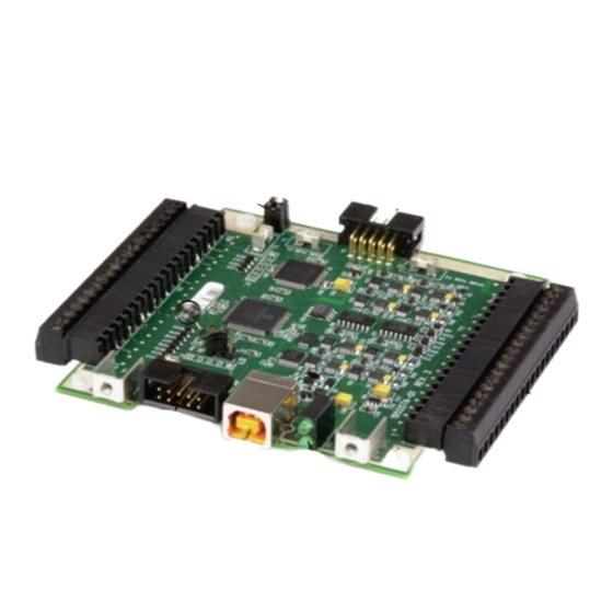
Page 11: Board Components
USB-7202 User's Guide Functional Details Board components The USB-7202 components are shown in Figure 2. Trigger/Sync connector USB connector Pins 1-20 Pins 21-40 Pins 1-20 Trigger jumper (P6) Pull-up/down jumper JP1 Trigger jumper (P7) Power LED (top) and Status LED (bottom) -
Page 12: Trigger/Sync Connector
SYNC/TRIG connector. Refer to Figure 2 on page 11 for the location of this jumper. LED indicators The USB-7202 has LEDs for power and communication status. See Figure 2 on page 11 for the location of each LED. LED type... -
Page 13: Screw Terminals
USB-7202 User's Guide Functional Details Screw terminals Screw terminal connections in shown in Figure 4. Figure 4. Screw terminal pinout Use 16 AWG to 30 AWG when making screw terminal connections. Signal connections Analog input You can connect up to eight analog input connections to screw terminals through . -
Page 14: Sync I/O
The USB-7202 alone draws 150 mA of current from the USB +5 V supply. Once you start running applications with the USB-7202, each DIO bit can draw up to 2.5 mA. The maximum amount of +5 V current available for experimental use, over and above that required by the USB-7202, is the difference between the total current requirement of the USB-7202 (based on the application) and the allowed current draw of the computer platform (500 mA for desktop computers and self-powered hubs). -
Page 15: Ground
The primary error sources in the USB-7202 are offset and gain. Nonlinearity is small in the USB-7202, and is not significant as an error source with respect to offset and gain. Figure 6 shows an ideal, error-free, USB-7202 transfer function. The typical calibrated accuracy of the USB- 7202 is range-dependent, as explained in the Specifications chapter on page 19. - Page 16 Combining these two error sources in Figure 9, we have a plot of the error band of the USB-7202 at ±full scale (±10 V). This plot is a graphical version of the typical accuracy specification of the product.
-
Page 17: Synchronized Operations
Figure 9. Error band plot Synchronized operations You can connect the SYNC pin of two USB-7202 devices together in a master/slave configuration and acquire data from the analog inputs of both devices using one clock. When the SYNC pin is configured as an output, the internal A/D pacer clock signal is sent to the screw terminal. -
Page 18: Mechanical Drawing
USB-7202 User's Guide Functional Details Mechanical drawing Figure 10. Circuit board dimensions... -
Page 19: Specifications
Chapter 4 Specifications All specifications are subject to change without notice. Typical for 25 °C unless otherwise specified. Specifications in italic text are guaranteed by design. Analog input Table 1. Analog input specifications Parameter Conditions Specification A/D converter type 16-bit successive approximation type Number of channels 8 single-ended Input configuration... -
Page 20: Digital Input/Output
USB-7202 User's Guide Specifications Table 4 summarizes the noise performance for the USB-7202. Noise distribution is determined by gathering 50 K samples with inputs tied to ground at the user connector. Samples are gathered at the maximum specified sampling rate of 50 kS/s. -
Page 21: External Clock Input/Output
USB-7202 User's Guide Specifications External clock input/output Table 7. External clock I/O specifications Parameter Conditions Specification Pin name SYNC Pin type Bidirectional Software-selectable direction Output Outputs internal A/D pacer clock. Input Receives A/D pacer clock from external source. Input clock rate... -
Page 22: Microcontroller
300 mA max Note 5: This is the total current requirement for the USB-7202, which includes up to 10 mA for the status LED. Note 6: "Self-powered hub" refers to a USB hub with an external power supply. Self-powered hubs allow a connected USB device to draw up to 500 mA. -
Page 23: Environmental
USB-7202 User's Guide Specifications Environmental Table 14. Environmental specifications Parameter Specification Operating temperature range 0 °C to 70 °C Storage temperature range –40 °C to 70 °C Humidity 0% to 90% non-condensing Mechanical Table 15. Mechanical specifications Parameter Specification Dimensions (L × W × H) 90.17 ×... -
Page 24: Oem Connector And Pinout (P4)
USB-7202 User's Guide Specifications OEM connector and pinout (P4) Table 18. OEM connector specifications Parameter Specification Connector type 10 position 2.54 mm (0.1 in.) box header Table 19. OEM connector pinout Signal Name Signal Name D– N/C (do not connect anything to this pin) - Page 25 Measurement Computing Corporation NI Hungary Kft 10 Commerce Way H-4031 Debrecen, Hátar út 1/A, Hungary Norton, Massachusetts 02766 Phone: +36 (52) 515400 (508) 946-5100 Fax: +36 (52) 515414 Fax: (508) 946-9500 http://hungary.ni.com/debrecen E-mail: info@mccdaq.com www.mccdaq.com...
Need help?
Do you have a question about the USB-7202 and is the answer not in the manual?
Questions and answers