Sign In
Upload
Download
Table of Contents
Contents
Add to my manuals
Delete from my manuals
Share
URL of this page:
HTML Link:
Bookmark this page
Add
Manual will be automatically added to "My Manuals"
Print this page
×
Bookmark added
×
Added to my manuals
Manuals
Brands
LEGRAND Manuals
UPS
1.1KVA
User manual
LEGRAND 1.1KVA User Manual
Line interactive sinewave ups, uninterruptible power supply system
Hide thumbs
1
Table Of Contents
2
3
4
5
6
7
8
9
10
11
12
13
14
15
16
17
18
19
20
21
22
23
24
25
26
27
28
29
30
page
of
30
Go
/
30
Contents
Table of Contents
Troubleshooting
Bookmarks
Table of Contents
Table of Contents
Important Safety Warnings
Transportation and Storage
Preparation
Installation
Operation
Maintenance, Service and Faults
Avertissements de Sécurité Importants
Transport Et Stockage
Préparation
Installation
Fonctionnement
Maintenance, Service Et Défauts
1 Installation and Setup
Unpacking and Inspection
Rear Panel
Operating Principle
Installing the UPS
Setting up the UPS
Battery Replacement
Replacement Battery Assembly
2 Operations
Button Operations
LCD Panel
Audible Alarms
LCD Panel Index
Operating Mode Descriptions
UPS Settings
Fault Reference Codes
Warning Indicators
4 Troubleshooting
5 Maintenance and Storage
Maintenance
Storage
6 Specifications
Input
Output
Efficiency
Battery
Protection
Alarm
Physical
Environment
Management
Expandable Battery Box Specification
Advertisement
Quick Links
1
Maintenance, Service and Faults
2
Battery Replacement
3
Lcd Panel
4
Audible Alarms
5
Troubleshooting
6
Alarm
Download this manual
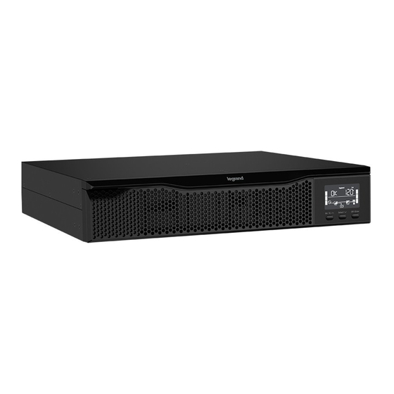
Line Interactive Sinewave UPS
1.1KVA | 1.5KVA | 2KVA | 3KVA Models
Uninterruptible Power Supply System
User Manual
I-00886 Rev A
Table of
Contents
Previous
Page
Next
Page
1
2
3
4
5
Advertisement
Table of Contents
Need help?
Do you have a question about the 1.1KVA and is the answer not in the manual?
Ask a question
Questions and answers
Related Manuals for LEGRAND 1.1KVA
UPS LEGRAND Trimod 10 kVA Operating And Maintenance Manual
(89 pages)
UPS LEGRAND 10 KVA Installation Manual
(48 pages)
UPS LEGRAND PREMIUS User And Installation Manual
1-10 kva (51 pages)
UPS LEGRAND NUMERIC Valura 1-3 kVA IBB Quick Setup Manual
(2 pages)
UPS LEGRAND Inform GUARDIAN 1000A User Manual
Line-interactive ups (12 pages)
UPS LEGRAND Inform GUARDIAN 600A User Manual
Line-interactive ups (12 pages)
UPS LEGRAND KEOR SPE TOWER Series Installation And User Manual
(164 pages)
UPS LEGRAND Keor T Series Operating Manual
(65 pages)
UPS LEGRAND KEOR COMPACT Installation And User Manual
(58 pages)
UPS LEGRAND KEOR LINE RT1500 VA Installation Manual
(144 pages)
UPS LEGRAND Niky 800 Installation Manual
(84 pages)
UPS LEGRAND Niky 1000 Installation Manual
(64 pages)
UPS LEGRAND KEOR MULTIPLUG 600 VA Installation Manual
(88 pages)
UPS LEGRAND DAKER DK Plus Series Installation Manual
1 kva - 3 kva (28 pages)
UPS LEGRAND DAKER DK Plus 3 101 71 Installation Manual
1 kva - 2 kva - 3 kva (196 pages)
UPS LEGRAND DAKER DK Plus 3 101 73 Installation Manual
5 kva - 6 kva - 10 kva (220 pages)
This manual is also suitable for:
1.5kva
2kva
3kva
1kva series
2kva series
1.5kva series
...
Show all
3kva series
Table of Contents
Print
Rename the bookmark
Delete bookmark?
Delete from my manuals?
Login
Sign In
OR
Sign in with Facebook
Sign in with Google
Upload manual
Upload from disk
Upload from URL


Need help?
Do you have a question about the 1.1KVA and is the answer not in the manual?
Questions and answers