Sign In
Upload
Manuals
Brands
FLENDER Manuals
Industrial Equipment
BIPEX-S BHH-W
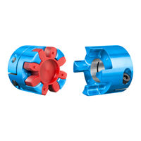
FLENDER BIPEX-S BHH-W Couplings Manuals
Manuals and User Guides for FLENDER BIPEX-S BHH-W Couplings. We have
2
FLENDER BIPEX-S BHH-W Couplings manuals available for free PDF download: Assembly And Operating Instructions Manual, Operating Instructions Manual
FLENDER BIPEX-S BHH-W Assembly And Operating Instructions Manual (68 pages)
Brand:
FLENDER
| Category:
Industrial Equipment
| Size: 1 MB
Table of Contents
Table of Contents
3
Introduction
11
Legal Information
11
About These Instructions
12
Text Attributes
12
Copyright
13
Safety Instructions
15
General Information
15
Intended Use
16
Table 2-1 General Warnings
16
General Warning Notices
17
Description
19
Figure 3-1 Type BNN
20
Figure 3-2 Type BGG
20
Figure 3-3 Type BCC
21
Figure 3-4 Type BHH
21
Figure 3-5 Type BKK
22
Figure 3-6 Type BCS
22
Figure 3-7 Type BHH-W
23
Application Planning
25
Transport of the Coupling
25
Storage of the Coupling
25
Figure 4-1 Transport Symbols
25
Table 4-1 Types of Preservative Agents for Long-Term Storage
26
Assembly
27
Preparatory Work
27
Assembling the Coupling
27
Assembling the Coupling Parts
28
Attach the Coupling Part N (1) with Parallel Key to the Shaft
28
Attaching Coupling Part G (2), C (3), H (4) or K (5) to the Shaft with a Clamping Connection
29
Attach Coupling Part S (6) to the Hollow Shaft with a Clamping Connection
29
Plug-In Assembly of the Coupling Halves
29
Plug-In Assembly of Types BNN, BGG, BCC, BHH, BKK and BCS
30
Plug-In Assembly of Type BHH-W
30
Aligning the Coupling
30
Purpose of Alignment
30
Possible Misalignment
31
Axial Misalignment
31
Angular Misalignment
31
Figure 5-1 Possible Misalignment
31
Radial Misalignment
32
Commissioning
33
Operation
35
Normal Operation of the Coupling
35
Faults - Causes and Rectification
35
Procedure in the Event of Malfunctions
35
Identifying the Fault Cause
35
Possible Faults
36
Possible Causes
37
Unsuitable Coupling
37
Assembly-Related Causes
37
Table 7-1 Table of Faults
37
Maintenance-Related Causes
38
Specific Installation-Related and Maintenance-Related Causes
38
Correcting Faults
38
Replacing Wearing Parts
38
Correcting the Changed Alignment
38
Servicing
41
Maintenance Intervals
41
Table 8-1 Maintenance Intervals
41
Maximum Permissible Torsional Backlash
42
Replacing Wearing Parts
42
Table 8-2 Maximum Permissible Torsional Backlash for the BIPEX-S Coupling
42
Figure 8-1 Markings for Calculating the Torsional Backlash
42
Removing Coupling Part N (1)
43
Removing Coupling Part G (2), C (3), H (4) or K (5)
43
Removing Coupling Part S (6)
44
Service and Support
45
Contact
45
Disposal
47
Spare Parts
49
Ordering Spare Parts
49
Spare Parts Drawing and Spare Parts List
50
Type BNN
50
Table 11-1 Spare Parts List for Type BNN
50
Figure 11-1 Spare Parts Drawing for Type BNN
50
Type BGG
51
Table 11-2 Spare Parts List for Type BGG
51
Figure 11-2 Spare Parts Drawing for Type BGG
51
Type BCC
52
Table 11-3 Spare Parts List for Type BCC
52
Figure 11-3 Spare Parts Drawing for Type BCC
52
Type BHH
53
Table 11-4 Spare Parts List for Type BHH
53
Figure 11-4 Spare Parts Drawing for Type BHH
53
Type BKK
54
Table 11-5 Spare Parts List for Type BKK
54
Figure 11-5 Spare Parts Drawing for Type BKK
54
Type BCS
55
Table 11-6 Spare Parts List for Type BCS
55
Figure 11-6 Spare Parts Drawing for Type BCS
55
Type BHH-W
56
Table 11-7 Spare Parts List for Type BHH-W
56
Figure 11-7 Spare Parts Drawing for Type BHH-W
56
Technical Data
57
Speeds, Geometry Data and Weights
57
Type BNN
57
Figure A-1 BNN Type
57
Type BGG
58
Table A-1 Geometry Data and Weights of BNN Type
58
Figure A-2 BGG Type
58
Type BCC
59
Table A-2 Geometry Data and Weights of Type BGG
59
Table A-3 Geometry Data and Weights of Type BCC
59
Figure A-3 BCC Type
59
Type BHH
60
Type BKK
60
Table A-4 Geometry Data and Weights of Type BHH
60
Figure A-4 BHH Type
60
Figure A-5 BKK Type
60
Type BCS
61
Table A-5 Geometry Data and Weights of Type BKK
61
Table A-6 Geometry Data and Weights of Type BCS
61
Figure A-6 BCS Type
61
Type BHH-W
62
Shaft Misalignment Values During Operation
62
Table A-7 Geometry Data and Weights of Type BHH-W
62
Figure A-7 BHH-W Type
62
Table A-8 Maximum Permissible Shaft Misalignment Values During Operation
63
Tightening Torques and Widths A/F
64
Tightening Procedure
64
Table A-10 Tightening Procedure
64
Cam Rings
65
Use and Storage of the Cam Rings
65
BIPEX-S Cam Ring (20)
65
Table A-11 BIPEX-S Cam Ring
65
Advertisement
FLENDER BIPEX-S BHH-W Operating Instructions Manual (66 pages)
FLENDER COUPLINGS
Brand:
FLENDER
| Category:
Industrial Equipment
| Size: 1 MB
Table of Contents
Safety Instructions
4
Table of Contents
5
1 Introduction
9
About These Instructions
9
Text Attributes
9
Copyright
9
Service and Support
9
2 Safety Instructions
11
General Information
11
Intended Use
12
General Warning Notices
13
Spare Parts
13
3 Description
15
Figure 3-1 Type BNN
16
Figure 3-2 Type BGG
17
Figure 3-3 Type BCC
17
Figure 3-4 Type BHH
18
Figure 3-5 Type BKK
19
Figure 3-6 Type BCS
20
Figure 3-7 Type BHH-W
21
4 Application Planning
23
Transport of the Coupling
23
Storage of the Coupling
23
Figure 4-1 Transport Symbols
23
Table 4-1 Types of Preservative Agents for Long-Term Storage
24
5 Assembly
25
Preparatory Work
25
Assembling the Coupling
26
Assembling the Coupling Parts
26
Attach the Coupling Part N (1) with Parallel Key to the Shaft
26
Attaching Coupling Part G (2), C (3), H (4) or K (5) to the Shaft with a Clamping Connection
27
Attach Coupling Part S (6) to the Hollow Shaft with a Clamping Connection
27
Plug-In Assembly of the Coupling Halves
28
Plug-In Assembly of Types BNN, BGG, BCC, BHH, BKK and BCS
28
Plug-In Assembly of Type BHH-W
28
Aligning the Coupling
29
Purpose of Alignment
29
Possible Misalignment
29
Figure 5-1 Possible Misalignment
29
Axial Misalignment
30
Angular Misalignment
30
Radial Misalignment
30
6 Commissioning
31
7 Operation
33
Normal Operation of the Coupling
33
Faults - Causes and Rectification
33
Procedure in the Event of Malfunctions
33
Identifying the Fault Cause
33
Possible Faults
34
Possible Causes
35
Correcting Faults
36
Replacing Wearing Parts
36
Correcting the Changed Alignment
37
8 Servicing
39
Maintenance Intervals
39
Maximum Permissible Torsional Backlash
40
Replacing Wearing Parts
40
Figure 8-1 Markings for Calculating the Torsional Backlash
40
Removing Coupling Part N (1)
41
Removing Coupling Part G (2), C (3), H (4) or K (5)
42
Removing Coupling Part S (6)
42
9 Service and Support
43
Contact
43
10 Disposal
45
11 Spare Parts
47
Ordering Spare Parts
47
Spare Parts Drawing and Spare Parts List
48
Type BNN
48
Figure 11-1 Spare Parts Drawing for Type BNN
48
Type BGG
49
Figure 11-2 Spare Parts Drawing for Type BGG
49
Type BCC
50
Figure 11-3 Spare Parts Drawing for Type BCC
50
Type BHH
51
Figure 11-4 Spare Parts Drawing for Type BHH
51
Type BKK
52
Figure 11-5 Spare Parts Drawing for Type BKK
52
Type BCS
53
Type BHH-W
54
Technical Data
55
Speeds, Geometry Data and Weights
55
Type BNN
55
Type BGG
56
A.1.2 Type BGG
56
Type BCC
57
A.1.3 Type BCC
57
Type BHH
58
A.1.4 Type BHH
58
Type BKK
59
A.1.5 Type BKK
59
Type BCS
60
A.1.6 Type BCS
60
Type BHH-W
61
A.1.7 Type BHH-W
61
Shaft Misalignment Values During Operation
62
Tightening Torques and Widths A/F
63
Tightening Procedure
63
Cam Rings
64
Use and Storage of the Cam Rings
64
BIPEX-S Cam Ring (20)
64
A.5 Cam Rings
64
Advertisement
Related Products
FLENDER BIPEX-S
FLENDER BIPEX-S BNN
FLENDER BIPEX-S BGG
FLENDER BIPEX-S BCC
FLENDER BIPEX-S BHH
FLENDER BIPEX-S BKK
FLENDER BIPEX-S BCS
FLENDER BIPEX BWN
FLENDER BIPEX BWT
FLENDER BIPEX BNT
FLENDER Categories
Industrial Equipment
Accessories
Sander
Adapter
Engine
More FLENDER Manuals
Login
Sign In
OR
Sign in with Facebook
Sign in with Google
Upload manual
Upload from disk
Upload from URL