
Related Manuals for FLENDER BIPEX-S BNN


Summary of Contents for FLENDER BIPEX-S BNN
- Page 1 BIPEX-S Assembly and operating instructions M3410-01en Edition 09/2022 BNN, BGG, BCC, BHH, BKK, BCS, BHH-W...
- Page 2 Original assembly and operating instructions M3410-01 Edition 09/2022 20/10/2022 Copyright (©2022 Flender GmbH) 09:26:00...
-
Page 3: Table Of Contents
Table of contents Introduction...............................11 Legal information ........................11 About these instructions......................12 Text attributes ..........................12 Copyright..........................13 Safety instructions ...........................15 General information .........................15 Intended use ..........................16 General warning notices ......................17 Description ..............................19 Application planning ..........................25 Transport of the coupling ......................25 Storage of the coupling ......................25 Assembly..............................27 Preparatory work........................27 Assembling the coupling ......................27... - Page 4 Table of contents Normal operation of the coupling .....................35 Faults - causes and rectification ....................35 7.2.1 Procedure in the event of malfunctions..................35 7.2.2 Identifying the fault cause ......................35 7.2.2.1 Possible faults ..........................36 7.2.2.2 Possible causes ........................37 7.2.2.2.1 Unsuitable coupling........................37 7.2.2.2.2 Assembly-related causes ......................37 7.2.2.2.3 Maintenance-related causes....................38...
- Page 5 Table of contents A.1.2 Type BGG ..........................58 A.1.3 Type BCC ..........................59 A.1.4 Type BHH ..........................60 A.1.5 Type BKK ..........................60 A.1.6 Type BCS..........................61 A.1.7 Type BHH-W ..........................62 Shaft misalignment values during operation ................62 Tightening torques and widths A/F ..................64 Tightening procedure .......................64 Cam rings..........................65 A.5.1 Use and storage of the cam rings ....................65...
- Page 6 Table of contents Edition 09/2022 M3410-01en...
- Page 7 List of tables Table 2-1 General warnings ........................15 Table 4-1 Types of preservative agents for long-term storage..............26 Table 7-1 Table of faults..........................36 Table 8-1 Maintenance intervals ........................41 Table 8-2 Maximum permissible torsional backlash for the BIPEX-S coupling ..........42 Table 11-1 Spare parts list for type BNN .....................50 Table 11-2 Spare parts list for type BGG ....................51 Table 11-3...
- Page 8 List of tables Edition 09/2022 M3410-01en...
- Page 9 List of figures Figure 3-1 Type BNN ..........................20 Figure 3-2 Type BGG ..........................20 Figure 3-3 Type BCC ..........................21 Figure 3-4 Type BHH ..........................21 Figure 3-5 Type BKK ..........................22 Figure 3-6 Type BCS ..........................22 Figure 3-7 Type BHH-W ..........................23 Figure 4-1 Transport symbols........................25 Figure 5-1 Possible misalignment........................31 Figure 8-1 Markings for calculating the torsional backlash................42 Figure 11-1 Spare parts drawing for type BNN .....................50 Figure 11-2...
- Page 10 List of figures Edition 09/2022 M3410-01en...
-
Page 11: Introduction
Introduction Legal information 1.1 Legal information Warning system These instructions contain information you must observe for your own personal safety as well as to avoid damage to property and persons. The information regarding your personal safety is highlighted with a warning triangle. Information exclusively regarding property dam- age alone is not marked with a warning triangle. -
Page 12: About These Instructions
Please note the following: WARNING Flender products are only suitable for the uses set out in the catalogue and associated technical documentation. If third-party products and components are used, these must be recommended and/or authorised by Flender. Safe and flawless operation of the products requires proper transport, proper storage, setup, assembly, installation, commissioning, operation and maintenance. -
Page 13: Copyright
(1) Numbers in brackets are part numbers. Copyright 1.4 Copyright The copyright for these instructions is held by Flender. These instructions must not be used wholly or in parts without our authorisation or be given to third parties. If you have any technical queries, please contact our factory or one of our service outlets (refer to Service and support (Page 45)). - Page 14 Introduction 1.4 Copyright Edition 09/2022 M3410-01en...
-
Page 15: Safety Instructions
Only the knowledge of these instructions can avoid faults on the coupling and ensure fault- free and safe operation. Non-adherence to the instructions can cause product or property damage or personal injury. Flender does not accept any liability for damage or operating fail- ures that are due to non-adherence to these instructions. -
Page 16: Intended Use
Safety instructions 2.2 Intended use ANSI Warning Warning – hand injuries Table 2-1: General warnings Explanation regarding Machinery Directive 2006/42/EC The couplings described here are “components” in accordance with the Machinery Directive and do not require a Declaration of Incorporation. Protective clothing In addition to the generally prescribed personal protective equipment (safety shoes, overalls, helmet, etc.), also wear suitable protective gloves and safety glasses when handling the coupling. -
Page 17: General Warning Notices
Safety instructions 2.3 General warning notices • Use only original replacement parts from Flender. Flender only accepts liability for ori- ginal replacement parts from Flender. Other replacement parts are not tested and approved by Flender. Non-approved re- placement parts may possibly change the design characteristics of the coupling and thus impact active and/or passive safety. - Page 18 Safety instructions 2.3 General warning notices Edition 09/2022 M3410-01en...
-
Page 19: Description
These instructions describe the assembly and operation of a BIPEX-S coupling arranged ho- rizontally with a shaft-hub connection made by a cylindrical or conical bore with a parallel key or by various clamping connections. Please consult Flender if you want to use a different type of installation. -
Page 20: Figure 3-1 Type Bnn
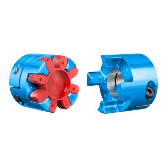
Description The diagrams show the various types with their constituent parts and their part numbers. Figure 3-1: Type BNN Coupling part N Set screw Cam ring Figure 3-2: Type BGG Coupling part G Cylinder-head screw Cam ring Edition 09/2022 M3410-01en... -
Page 21: Figure 3-3 Type Bcc
Description Figure 3-3: Type BCC Coupling part C Cylinder-head screw Cam ring Figure 3-4: Type BHH Coupling part H Cylinder-head screw Cam ring M3410-01en Edition 09/2022... -
Page 22: Figure 3-5 Type Bkk
Description Figure 3-5: Type BKK Coupling part K Cylinder-head screw Cam ring Figure 3-6: Type BCS Coupling part C Coupling part S Cylinder-head screw Cylinder-head screw Cam ring Clamping taper Edition 09/2022 M3410-01en... -
Page 23: Figure 3-7 Type Bhh-W
Description Figure 3-7: Type BHH-W Coupling part H Spacer W Cylinder-head screw Cam ring M3410-01en Edition 09/2022... - Page 24 Description Edition 09/2022 M3410-01en...
-
Page 25: Application Planning
Application planning Check the delivery for damage and for completeness. Report any damage and/or missing parts to Flender immediately. The coupling is delivered in individual parts and preassembled groups. Preassembled groups may not be dismantled. Transport of the coupling 4.1 Transport of the coupling... -
Page 26: Table 4-1 Types Of Preservative Agents For Long-Term Storage
Application planning 4.2 Storage of the coupling • Do not store the coupling together with corrosive chemicals, acids, caustic solutions, etc. • If the coupling contains elastomer components, ensure that there are no devices in the storage room that produce ozone, such as fluorescent lights, mercury vapour lamps or high-voltage electrical equipment. -
Page 27: Assembly
Assembly Assembly of the coupling comprises the following steps: • Preparatory work (Page 27) • Mounting the coupling (Page 27) • Aligning the coupling (Page 30) WARNING Risk of injury due to coupling rupture If you do not observe the information stipulated here regarding assembly, this can lead to bursting of the coupling during operation. -
Page 28: Assembling The Coupling Parts
Assembly 5.2 Assembling the coupling NOTICE Property damage Damage to the shaft end, the coupling parts and/or the parallel key. • Note the handling instructions regarding assembly of the coupling parts. Assembly of the coupling comprises the following steps: • Assembling the coupling parts (Page 28) •... -
Page 29: Attaching Coupling Part G (2), C (3), H (4) Or K (5) To The Shaft With A Clamping Connection
Assembly 5.2 Assembling the coupling 5.2.1.2 Attaching coupling part G (2), C (3), H (4) or K (5) to the shaft with a clamping connection 5.2 Assembling the coupling Procedure 1. Undo the cylinder-head screws (12). 2. Clean the bores and shaft ends. 3. -
Page 30: Plug-In Assembly Of Types Bnn, Bgg, Bcc, Bhh, Bkk And Bcs
Assembly 5.2 Assembling the coupling • Plug-in assembly of type BHH-W (Page 30) 5.2.2.1 Plug-in assembly of types BNN, BGG, BCC, BHH, BKK and BCS 5.2 Assembling the coupling Procedure 1. Push the cam ring (20) onto a coupling part. 2. Push the coupling halves together. When doing this, pay attention to the dimension S from section Speeds, geometry data and weights (Page 57). -
Page 31: Possible Misalignment
Assembly 5.3 Aligning the coupling 5.3.2 Possible misalignment 5.3 Aligning the coupling The following types of misalignment can occur: Figure 5-1: Possible misalignment ① Axial misalignment (ΔKa) ② Angular misalignment (ΔKw) ③ Radial misalignment (ΔKr) NOTICE Property damage The specified permissible values for axial, angular and/or radial misalignment may not ap- pear simultaneously. -
Page 32: Radial Misalignment
Assembly 5.3 Aligning the coupling 5.3.2.3 Radial misalignment 5.3 Aligning the coupling Determine the value ΔKr. The determined value ΔKr may not exceed the value ΔKr perm You can find the permissible radial misalignment ΔKr in section Shaft misalignment val- perm ues during operation (Page 62). -
Page 33: Commissioning
Commissioning In order to ensure safe commissioning, carry out various tests prior to commissioning. Testing before commissioning WARNING Danger Overload conditions can occur during the commissioning of the coupling. The coupling can burst and metal parts can be flung out. There is a risk of fatal injury from flying fragments. •... - Page 34 Commissioning Edition 09/2022 M3410-01en...
-
Page 35: Operation
Operation Normal operation of the coupling 7.1 Normal operation of the coupling The coupling runs quietly and shock-free during normal operation. Faults - causes and rectification 7.2 Faults - causes and rectification A form of behaviour which is different to normal operation is classed as a fault and has to be rectified immediately. -
Page 36: Possible Faults
Operation 7.2 Faults - causes and rectification WARNING Physical injury Injury from rotating parts. • Only carry out work on the coupling when it is not moving. • Secure the drive unit against being operated accidentally. • Attach a notice to the switch stating clearly that work is being carried out on the coup- ling. -
Page 37: Possible Causes
Operation 7.2 Faults - causes and rectification Fault Cause Rectification Presence of vibration Incorrect assembly of the coupling. Reassemble the coupling in accord- ance with these instructions. Check the possible causes given in sections Assembly-related causes Please observe all the stipulations and (Page 37) and Specific installation-re- requirements given in chapter As- lated and maintenance-related causes... -
Page 38: Maintenance-Related Causes
7.2 Faults - causes and rectification • Stipulated maintenance intervals not adhered to. • Spare parts that were used were not original spare parts from Flender. • Flender spare parts that were used were old or damaged. • Leak in the area of the coupling not detected so that chemically aggressive substances damage the coupling. - Page 39 Operation 7.2 Faults - causes and rectification 3. Check the locking elements that prevent axial movements and correct these as required. 4. Realign the coupling. M3410-01en Edition 09/2022...
- Page 40 Operation 7.2 Faults - causes and rectification Edition 09/2022 M3410-01en...
-
Page 41: Servicing
Servicing Maintenance intervals 8.1 Maintenance intervals WARNING Danger of injury due to bursting of the coupling The coupling can burst if the maintenance intervals are not adhered to. There is a risk of fatal injury from flying fragments. • Please observe all the stipulations concerning maintenance of the coupling in this sec- tion. -
Page 42: Maximum Permissible Torsional Backlash
Servicing 8.2 Maximum permissible torsional backlash Maximum permissible torsional backlash 8.2 Maximum permissible torsional backlash In order to calculate the torsional backlash, rotate one coupling part without applying torque up to the stop. Mark both of the coupling halves in the way shown in the diagram below. Turn the coupling part in the opposite direction up to the stop. -
Page 43: Removing Coupling Part N (1)
Servicing 8.4 Removing coupling part N (1) Removing coupling part N (1) 8.4 Removing coupling part N (1) WARNING Danger from burners and hot coupling parts Risk of injury due to burners and hot surfaces. • Wear suitable protective equipment (gloves, safety goggles). Procedure 1. -
Page 44: Removing Coupling Part S (6)
Servicing 8.6 Removing coupling part S (6) Removing coupling part S (6) 8.6 Removing coupling part S (6) Procedure 1. Move the coupled machines apart. 2. Secure the coupling parts to prevent them from falling. 3. Undo the cylinder-head screw (13). 4. Pull off the coupling part S (6) together with the clamping taper (61). Use suitable lifting gear when doing this. -
Page 45: Service And Support
Customer Service addresses: Flender GmbH Schlavenhorst 100 46395 Bocholt Germany Tel.: +49 (0)2871/92-0 Fax.: +49 (0)2871/92-2596 Flender GmbH (http://www.flender.com/) More information Further information about service and support can be found on the Internet: Service & Support (https://www.flender.com/service) M3410-01en Edition 09/2022... - Page 46 Service and support 9.1 Contact Edition 09/2022 M3410-01en...
-
Page 47: Disposal
Disposal Disposal of the coupling Dispose of the coupling parts according to applicable national regulations or recycle them. M3410-01en Edition 09/2022... - Page 48 Disposal Edition 09/2022 M3410-01en...
-
Page 49: Spare Parts
By stocking the most important replacement parts at the installation site you can ensure that the coupling is ready for use at any time. Use only original replacement parts from Flender. Flender only accepts liability for original replacement parts from Flender. -
Page 50: Spare Parts Drawing And Spare Parts List
Spare parts 11.2 Spare parts drawing and spare parts list 11.2 Spare parts drawing and spare parts list 11.2 Spare parts drawing and spare parts list 11.2.1 Type BNN 11.2 Spare parts drawing and spare parts list Figure 11-1: Spare parts drawing for type BNN Part number Designation Coupling part N... -
Page 51: Type Bgg
Spare parts 11.2 Spare parts drawing and spare parts list 11.2.2 Type BGG 11.2 Spare parts drawing and spare parts list Figure 11-2: Spare parts drawing for type BGG Part number Designation Coupling part G Cylinder-head screw Cam ring Table 11-2: Spare parts list for type BGG M3410-01en Edition 09/2022... -
Page 52: Type Bcc
Spare parts 11.2 Spare parts drawing and spare parts list 11.2.3 Type BCC 11.2 Spare parts drawing and spare parts list Figure 11-3: Spare parts drawing for type BCC Part number Designation Coupling part C Cylinder-head screw Cam ring Table 11-3: Spare parts list for type BCC Edition 09/2022 M3410-01en... -
Page 53: Type Bhh
Spare parts 11.2 Spare parts drawing and spare parts list 11.2.4 Type BHH 11.2 Spare parts drawing and spare parts list Figure 11-4: Spare parts drawing for type BHH Part number Designation Coupling part H Cylinder-head screw Cam ring Table 11-4: Spare parts list for type BHH M3410-01en Edition 09/2022... -
Page 54: Type Bkk
Spare parts 11.2 Spare parts drawing and spare parts list 11.2.5 Type BKK 11.2 Spare parts drawing and spare parts list Figure 11-5: Spare parts drawing for type BKK Part number Designation Coupling part K Cylinder-head screw Cam ring Table 11-5: Spare parts list for type BKK Edition 09/2022 M3410-01en... -
Page 55: Type Bcs
Spare parts 11.2 Spare parts drawing and spare parts list 11.2.6 Type BCS 11.2 Spare parts drawing and spare parts list Figure 11-6: Spare parts drawing for type BCS Part number Designation Coupling part C Coupling part S Cylinder-head screw Cylinder-head screw Cam ring Clamping taper Table 11-6: Spare parts list for type BCS... -
Page 56: Type Bhh-W
Spare parts 11.2 Spare parts drawing and spare parts list 11.2.7 Type BHH-W 11.2 Spare parts drawing and spare parts list Figure 11-7: Spare parts drawing for type BHH-W Part number Designation Coupling part H Spacer W Cylinder-head screw Cam ring Table 11-7: Spare parts list for type BHH-W Edition 09/2022 M3410-01en... -
Page 57: Technical Data
Technical data Speeds, geometry data and weights Speeds, geometry data and weights In this section you can find dimension drawings and technical data for BIPEX-S couplings of the following types: • Type BNN (Page 57) • Type BGG (Page 58) • Type BCC (Page 59) •... -
Page 58: Type Bgg
Technical data Speeds, geometry data and weights 2) Size D1 / D2 ND1 / ND2 NL1 / NL2 Weight max. perm dev. +0.5 0.36 +0.5 0.53 +1.0 +1.0 +1.0 Table A-1: Geometry data and weights of BNN type Maximum bore for parallel keyway in accordance with DIN 6885/1. Weight applies to one coupling with maximum bore A.1.2 Type BGG Speeds, geometry data and weights... -
Page 59: Type Bcc
Technical data Speeds, geometry data and weights Size D1 / D2 ND1 / ND2 NL1 / NL2 Weight max. perm dev. +1.0 +1.0 Table A-2: Geometry data and weights of type BGG Weight applies to one coupling with maximum bore. A.1.3 Type BCC Speeds, geometry data and weights Figure A-3: BCC type ①... -
Page 60: Type Bhh
Technical data Speeds, geometry data and weights A.1.4 Type BHH Speeds, geometry data and weights Figure A-4: BHH type Coupling part H Size D1 / D2 NL1 / NL2 Weight max. perm dev. +0.5 0.02 +0.5 0.15 +0.5 0.35 +0.5 0.53 +1.0 0.98 +1.0 +1.0 Table A-4: Geometry data and weights of type BHH Weight applies to one coupling with maximum bore. -
Page 61: Type Bcs
Technical data Speeds, geometry data and weights Size D1 / D2 NL1 / NL2 Weight max. perm dev. 18.5 +0.5 0.11 +0.5 0.23 +0.5 0.57 +0.5 0.86 43.5 +1.0 +1.0 +1.0 Table A-5: Geometry data and weights of type BKK Weight applies to one coupling with maximum bore. A.1.6 Type BCS Speeds, geometry data and weights... -
Page 62: Type Bhh-W
Technical data Speeds, geometry data and weights A.1.7 Type BHH-W Speeds, geometry data and weights Figure A-7: BHH-W type Coupling part H Spacer W Size D1 / D2 NL1 / NL2 Weight max. perm dev. min. max. +0.5 3000 1.35 +0.5 3000 1.75 +0.5 3000 +0.5 3000 +1.0 3000 +1.0... -
Page 63: Table A-8 Maximum Permissible Shaft Misalignment Values During Operation
Technical data Shaft misalignment values during operation Size Shore hardness Permissible shaft misalignment Axial Radial Angular ΔKa ΔKr ΔKw ΔS perm perm perm perm Degrees 80 Shore A 0.19 0.38 92 Shore A 0.13 0.35 98 Shore A 0.08 0.31 64 Shore D 0.05 0.28... -
Page 64: Tightening Torques And Widths A/F
Technical data Tightening torques and widths A/F Tightening torques and widths A/F Tightening torques and widths A/F Size Model Model Model Model Model Model Model BHH-W Part 11 Part 12 Part 12 Part 12 Part 12 Part 12 Part 13 Part 12 0.75 10.5... -
Page 65: Cam Rings
Technical data Cam rings Cam rings Cam rings A.5.1 Use and storage of the cam rings Cam rings Note the following concerning the use and storage of the cam rings: • Storage possible for up to 5 years • Protect against direct sunlight, artificial light with a high UV‐content and extreme temper- atures •... - Page 66 Technical data Cam rings Edition 09/2022 M3410-01en...
- Page 68 BIPEX-S Assembly and operating instructions M3410-01en Edition 09/2022 Flender GmbH Alfred-Flender-Straße 77 46395 Bocholt Germany...
Need help?
Do you have a question about the BIPEX-S BNN and is the answer not in the manual?
Questions and answers