MSA Sirius Operating Manual
Multigas detector
Hide thumbs
Also See for Sirius:
- Instruction manual (15 pages) ,
- Instruction manual (434 pages) ,
- Instruction manual (62 pages)
Table of Contents
Advertisement
Quick Links
Sirius
MultiGas Detector
Operating Manual
In North America, to contact your nearest stocking location, dial toll-free 1-800-MSA-2222
To contact MSA International, dial 1-412-967-3354 or 1-800-MSA-7777
© MINE SAFETY APPLIANCES COMPANY 2005 - All Rights Reserved
This manual is available on the internet at www.msanet.com
Manufactured by
MSA INSTRUMENT DIVISION
P.O. Box 427, Pittsburgh, Pennsylvania 15230
(L) Rev 2
®
10048887
Advertisement
Table of Contents
Troubleshooting

Subscribe to Our Youtube Channel
Related Manuals for MSA Sirius


Summary of Contents for MSA Sirius
- Page 1 Sirius MultiGas Detector Operating Manual In North America, to contact your nearest stocking location, dial toll-free 1-800-MSA-2222 To contact MSA International, dial 1-412-967-3354 or 1-800-MSA-7777 © MINE SAFETY APPLIANCES COMPANY 2005 - All Rights Reserved This manual is available on the internet at www.msanet.com...
- Page 2 " " WARNING THIS MANUAL MUST BE CAREFULLY READ BY ALL INDIVIDUALS WHO HAVE OR WILL HAVE THE RESPONSIBILITY FOR USING OR SERVICING THE PRODUCT. Like any piece of complex equipment, this instrument will perform as designed only if it is used and serv- iced in accordance with the manufacturer’s instructions.
-
Page 3: Table Of Contents
Figure 3-2. Understanding the Display ..3-2 Turning ON the Sirius Multigas Detector ... .3-3 Last Cal Date ....... . .3-3 Fresh Air Set Up Option . - Page 4 " WARNING ......3-6 PID Alarms ........3-7 PID Bulb -Cal Now .
- Page 5 " WARNING ......3-24 Turning OFF the Sirius Multigas Detector ..3-25 Chapter 4, Setting up the Sirius Multigas Detector .
- Page 6 Troubleshooting ..... . .6-1 MSA Portable Instrument Warranty ....6-1 Cleaning and Periodic Checks .
- Page 7 Typical Performance Specifications ..7-2 Table 7-4. COMBUSTIBLE GAS - Cross Reference Factors for Sirius General-Purpose Calibration Using Calibration Cylinder (P/N 10045035) Set to 58% LEL Pentane Simulant ..7-2 Table 7-5.
- Page 8 Table 7-9. HYDROGEN SULFIDE - Cross Reference Factors for Sirius Calibration Using Calibration Cylinder (P/N10045035) ......7-7 Table 7-10. PID (appropriate models only) - Typical Performance Specifications .
-
Page 9: Instrument Safety And Certifications
Chapter 1, Instrument Safety and Certifications The Sirius Multigas Detector is for use by trained and qualified personnel. It is designed to be used when performing a hazard assessment to: • Assess potential worker exposure to combustible and toxic gases and vapors •... -
Page 10: Safety Limitations And Precautions
Carefully review the following safety limitations and precautions before placing this instrument in service: • The Sirius Multigas Detector is designed to: • Detect gases and vapors in air only • Detect only specified toxic gases for which a sensor is installed. - Page 11 In such cases, the instrument LockAlarm feature activates. Move away from contaminated area immediately. • Do not use the Sirius Multigas Detector to test for combustible or toxic gases in the following atmospheres as this may result in erroneous readings: •...
-
Page 12: Date Of Instrument Manufacture
Only MSA-authorized personnel may repair this unit; otherwise, damage may result. Date of Instrument Manufacture The date of manufacture of your Sirius Multigas Detector is coded into the instrument serial number. • The last three digits represent the month (the letter) and the year (the two-digit number). -
Page 13: Chapter 2, Pid Theory And Definitions
Chapter 2, PID Theory and Definitions To support the safe and effective operation of the Sirius Multigas Detector, MSA believes operators should have a working knowledge of how the instrument functions, not just how to make it work. The information presented in this section supplements the hands-on operational instruction provided in the rest of the manual for the PID. -
Page 14: Zero Gas
When background hydrocarbon vapors are present, MSA recommends using zero gas air or a carbon filter on the inlet to zero the unit (See Chapter 8, TABLE 8-1, Accessory Parts List). -
Page 15: Calculating A Response Factor
To determine a response factor for a target chemical, perform the following simple procedure: 1. Calibrate the Sirius Detector using isobutylene as the span gas. 2. On the monitor, set the sample gas name to isobutylene. 3. Apply a known concentration of the target chemical to the monitor and note the concentration reported in the display. -
Page 16: Warning
PID setup since PID response factors for a target chemical relative to Isobutylene are different depending on what ener- gy PID bulb is installed. See Chapter 3, “Using the Sirius Multigas Detector” for setup instructions. Failure to follow this warning can result in inaccurate readings that could... -
Page 17: Using The Sirius Multigas Detector
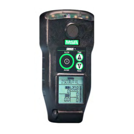
Chapter 3, Using the Sirius Multigas Detector Figure 3-1. Instrument Features... -
Page 18: Figure 3-2. Understanding The Display
Figure 3-2. Understanding the Display... -
Page 19: Turning On The Sirius Multigas Detector
6. Instrument warm-up period 7. Fresh Air Setup option. Last Cal Date The Sirius Multigas Detector is equipped with a “last successful calibration date” feature. The date shown is the last date that all installed sensors were successfully calibrated. "LAST CAL" is displayed with this date in the following format: •... -
Page 20: Fresh Air Set Up Option
Failure to follow this warning can result in serious personal injury or death. Persons responsible for the use of the Sirius Multigas Detector must determine whether or not the Fresh Air Setup option should be used. The user's abilities, training and normal work practices must be considered when making this decision. -
Page 21: Battery Life Indicator (Figure 3-3)
NOTE: Duration of remaining instrument operation during Battery Warning depends on ambient temperatures. • When the Sirius Multigas Detector goes into Battery Warning: • Battery Life indicator flashes • “BATT WRN” flashes every 15 seconds •... -
Page 22: Sensor Missing Alarm
Sensor Missing Alarm The Sirius Multigas Detector will enter the Sensor Missing alarm if the instrument detects that an enabled sensor is not properly installed in the instrument. For O 2 , CO, and H 2 S sensors, the Sensor Missing feature is checked when the instrument is turned ON and when leaving the Setup mode. -
Page 23: Pid Alarms
After approximately one minute, the unit automatically turns OFF. PID Alarms The Sirius Multigas Detector will enter the Ion Error, PID Error, PID Failed Span Cal, or the PID Comm Error if the instrument detects that the PID is not functioning properly. -
Page 24: Verifying Pump Operation
Verifying Pump Operation 1. Turn ON the Sirius Multigas Detector. • The pump motor starts fast and then slows down as the instrument adjusts the power to run the pump. 2. Once gas readings are displayed, plug the free end of the sampling line or probe. -
Page 25: To Clear An Alarm
If liquid is sucked into the instrument, read- ings will be inaccurate and the instrument could be dam- aged. We recommend the use of an MSA Sample Probe (P/N 10042621, 10042622, 10040589, or equivalent) contain- ing a special membrane filter, permeable to gas but imper- meable to water, to prevent such an occurrence. -
Page 26: Measuring Gas Concentrations
1. Turn ON the Sirius Multigas Detector in clean, fresh air. 2. Verify that readings indicate no gas is present. 3. Attach regulator (supplied with calibration kit) to the cylinder. 4. Connect tubing (supplied with calibration kit) to the regulator. -
Page 27: Warning
Figure 3-5b. Instrument in LEL Alarm The Sirius Multigas Detector can be equipped to detect combustible gases in the atmosphere. • Alarms sound when concentrations reach: • Alarm Setpoint or • 100% LEL (Lower Explosive Limit), 5% CH 4 . -
Page 28: Oxygen Measurements (% O2) (Figure 3-6)
OFF the instrument and turning it ON again. Oxygen Measurements (% O 2 ) (FIGURE 3-6) Figure 3-6a. Instrument in Oxygen Alarm Figure 3-6b. Instrument in Oxygen Alarm The Sirius Multigas Detector can be equipped to detect the amount of oxygen in the atmosphere. 3-12... -
Page 29: Toxic Gas And Voc Measurements (Figure 3-7)
• Alarms can be set to trigger on two different conditions: • Deficiency/too little oxygen (setpoints less than 20.8) • Enriched/too much oxygen (setpoints greater than 20.8). • When the alarm setpoint is reached for either of the above: • Alarm sounds •... -
Page 30: Confidence Flash
Figure 3-7b. Instrument in VOC Gas Alarm • The Sirius Multigas Detector can be equipped to detect: • Carbon Monoxide (CO) and/or • Hydrogen Sulfide (H 2 S) and/or • Volatile Organic Compounds (VOCs) in the atmosphere. • When the alarm setpoint is reached for Carbon Monoxide (CO) and/or Hydrogen Sulfide (H 2 S) and/or VOC: •... -
Page 31: Safe Led
Figure 3-8. Heartbeat Safe LED The Sirius Multigas Detector is equipped with an optional green "SAFE" LED which flashes every 15 seconds under the following conditions • The green SAFE LED is enabled • Instrument is on the normal Measure Gases page •... -
Page 32: Viewing Optional Displays (Figure 3-9)
Viewing Optional Displays (FIGURE 3-9) The FIGURE 3-9 diagram describes the flow for optional displays. Figure 3-9. Flow Diagram 3-16... -
Page 33: Peak Readings (Peak) (Figure 3-10)
Peak Readings (PEAK) (FIGURE 3-10) Figure 3-10. PEAK Readings on the Display • PEAK appears in the upper portion of the display to show the highest levels of gas recorded by the Sirius Detector since: • Turn-ON or • Peak readings were reset. -
Page 34: Short Term Exposure Limits (Stel) (Figure 3-12)
• This page shows the lowest level of oxygen recorded by the Sirius Multigas Detector since: • Turn-ON or • MIN reading was reset. • MIN appears in the upper portion of the display. • To reset the MIN Reading: 1. -
Page 35: Time Weighted Average (Twa) (Figure 3-13)
The STEL alarm is calculated over a 15-minute exposure. Calculation examples are as follows: • Assume the Detector has been running for at least 15 minutes: • 15-minute exposure of 35 PPM: (15 minutes x 35 PPM) = 35 PPM 15 minutes •... -
Page 36: To Reset The Twa
• When the amount of gas detected by the Sirius Multigas Detector is greater than the eight-hour TWA limit: • Alarm Sounds • Alarm Lights Flash • TWA flashes. To Reset the TWA: 1. Access the TWA page. 2. Press the RESET/ button. -
Page 37: Time And Date Display (Figure 3-14)
Time and Date Display (FIGURE 3-14) Figure 3-14 Time Display • The time appears on the display to show the current time of day in a 24-hour format. • The date appears on the display with the current date displayed in the following format: •... -
Page 38: Changing Response Factor
At any time, user can select the option display by pressing the ON-OFF/ACCEPT button. • The first five Response Factors in the list are called favorites (these can be set using our MSA FiveStar Link program). • The user has the option to turn OFF the PID (VOC detection), if desired. -
Page 39: Changing Pid Bulb Selection
4. Use the RESET/ button to scroll through the alphabet or numbers, and use the ON-OFF/ACCEPT button to select the letter and move on to the next letter. Changing PID Bulb Selection Several PID bulb options are available for this instrument. The two bulb options currently available are: •... -
Page 40: Warning
Response Factor, and/or the correct bulb, will result in erroneous readings that could lead to serious injury or death. Turning OFF the Sirius Multigas Detector Push and Hold the ON-OFF/ACCEPT button for three seconds. • Four audible beeps will be heard during the turn-off sequence. -
Page 41: Setting Up The Sirius Multigas Detector
Do not take battery packs into a hazardous area unless they are properly attached to the Sirius instrument! To remove the battery pack from the Sirius Multigas Detector: 1. Unscrew the captive screw from the bottom of the battery door. -
Page 42: Figure 4-1. Battery Pack Removal
Figure 4-1. Battery Pack Removal 2. Pull the battery pack out of the instrument by gripping the sides of the battery pack door and lifting it up and away from the unit. 3. For Alkaline battery packs: a. Pull the battery pack from the clip. Figure 4-2. -
Page 43: Battery Charging (Lithium-Ion Battery Pack Only)
Do not charge in a hazardous area. • The Sirius Multigas Detector must be turned OFF, or the battery pack may be removed from the instrument, prior to charging. NOTE: If the instrument is not turned OFF, the charger connection will turn OFF the instrument without warning. -
Page 44: Changing Instrument Settings
Many options can be set using the instrument buttons. • If the Sirius Multigas Detector was ordered with the optional datalogging, the MSA FiveStar LINK software can be used to set most of the instrument selections, including some that cannot be changed from the instrument's front panel buttons. -
Page 45: Figure 4-3.. Entering The Set-Up Mode
Figure 4-3.. Entering the Set-up Mode... -
Page 46: Instrument Alarm Bypass Options
5. New Password Setup (changes the password) Instrument Alarm Bypass Options The Sirius Multigas Detector (with software version 1.1 or higher) is equipped with a feature to disable or silence the visual, backlight, and audible options. If any of these options are disabled during instrument startup, the Sirius Detector displays: •... - Page 47 • Cal Lockout Enable: • To disable calibration, turn this feature ON • When ON, calibration is only accessible via the Setup mode and password (if enabled) • CAL Due Alert • To disable CAL Due messages, turn this feature OFF. •...
-
Page 48: Warning
• Low Alarm (sets the low CO alarm) • High Alarm (sets the high CO alarm) • STEL Alarm (if enabled) (sets the STEL CO alarm) • TWA Alarm (if enabled) (sets the TWA CO alarm) • Cal Gas (sets the expected CO calibration gas) 10.H 2 S Setup •... -
Page 49: Warning
NOTE: After set-up, the instrument will display: "Warning - 100 ppb increments - see manual". Press the ON/OFF button to acknowledge the warning and to continue. " WARNING " The VOC Auto-range displays readings in increments of 100 ppb from 0 to 9900 ppb. Do not rely on the value of the last two digits (00). -
Page 50: Chapter 5, Calibration
Chapter 5, Calibration Calibrating the Sirius Multigas Detector Each Sirius Multigas Detector is equipped with an Autocalibration feature to make unit calibration as easy as possible. The Autocalibration sequence resets instrument zeroes and adjusts sensor calibration for known concentrations of calibration gases. -
Page 51: To Calibrate The Sirius Multigas Detector
To Calibrate the Sirius Multigas Detector (FIGURE 5-1): Figure 5-1. Calibration Flow Chart 1. Turn ON the instrument and verify that battery has sufficient life. 2. Wait until the Measure Gases page appears. 3. Push and hold the RESET/ button until CAL ZERO? flashes on... -
Page 52: Figure 5-2A. Zero Flag
Figure 5-2a. Zero Flag Figure 5-2b. Zero Flag 4. Push the ON-OFF/ACCEPT button to zero the instrument. • Instrument must be in fresh air to perform the zero. • CAL ZERO flashes. NOTE: To skip the Zero procedure and move directly to the calibration span procedure, push the RESET/ button. -
Page 53: Figure 5-3A. Cal Flag
Figure 5-3a. CAL Flag Figure 5-3b. CAL Flag 5. Connect the appropriate calibration gas to the instrument by connecting one end of the tubing to the pump inlet on the instrument and the other end of tubing to the cylinder regulator (supplied in the calibration kit). -
Page 54: Autocalibration Failure
Autocalibration Failure If the Sirius Multigas Detector cannot calibrate one or more sensor(s), the instrument goes into the Autocalibration Failure Page and remains in alarm until the RESET button is pushed. Sensors that could not be calibrated are indicated by dashed lines on the concentration display. -
Page 55: Chapter 6, Warranty, Maintenance, And Troubleshooting
Chapter 6, Warranty, Maintenance, and Troubleshooting MSA Portable Instrument Warranty Warranty- ITEM WARRANTY PERIOD Chassis and electronics Two years All sensors, unless otherwise specified Two years PID, including ion chamber One year This warranty does not cover fuses. Certain other accessories not specifically listed here may have different warranty periods. -
Page 56: Cleaning And Periodic Checks
Cleaning and Periodic Checks As with all electronic equipment, the Sirius Multigas Detector will operate only if it is properly maintained. " WARNING "... -
Page 57: Cleaning Steps
• the PID shows increased sensitivity to humidity • the displayed PID reading is erratic. If you are operating the monitor in a high temperature, high humidity, or dirty environment, you may need to clean the lamp more frequently to maintain optimal performance. -
Page 58: Warning
Figure 6-1. Cleaning the PID Bulb 6. Open the Bulb Cleaning Kit (P/N 10049691), consisting of cleaning implements and laboratory-grade methanol. 7. Moisten a clean cotton swab with methanol. 8. Hold the middle of the bulb body securely in your thumb and fore- finger. -
Page 59: Replacing The Ion Chamber
16.Never touch the lens surface with your fingers. If contact occurs, repeat steps 6 through 13. 17.Gently insert the clean bulb, window first into the bulb sleeve of the instrument. " CAUTION " Do not apply excessive pressure when seating the bulb. Too much pressure may damage the detector and/or the bulb. - Page 60 Use the Ion Chamber Replacement Kit (P/N 10050783). " CAUTION " Remove and re-install the ion chamber in a clean, non-haz- ardous environment. 1. Turn OFF the instrument and, while in a non-hazardous and non- combustible area, remove the battery pack. 2.
-
Page 61: Figure 6-2B. Ion Chamber Removal
Figure 6-2b. Ion Chamber Removal 5. Using the 2.8-ounce container of ‘canned air’ found in the replacement kit, blow out any dust or dirt from the cell holder area (FIGURE 6-3a). NOTE: Hold the cleaner in a vertical position; do not shake. Hold the instrument upright and with two to three short bursts, blow any debris from the cell holder area. -
Page 62: Replacing The Filters
Figure 6-3a. Ion Chamber Housing Cleaning Figure 6-3b. Ion Chamber Cleaning 8. Snap the ion chamber into the cell holder, with the four small, round holes facing up as in FIGURE 6-4. 9. Replace the ion chamber cover, aligning the notch to ensure proper orientation. -
Page 63: Dust And Water Filter
Figure 6-4. Ion Chamber Installation 11. Replace the filter housing and tighten the screw. 12.Place the used ion chamber in the reclosable package and discard. 13.Turn ON the instrument and check the system for leaks by plugging the inlet with a finger. •... -
Page 64: Figure 6-5. Filter Installation
Figure 6-5. Filter Installation 5. Install the new water filter in the filter housing recess. 6. Replace the O-ring, being sure to press gently down on top of the water filter. NOTE: When replacing the water filter, carefully handle the new filter by the edges only, as it is easily torn. -
Page 65: Probe Filter
Failure to follow the above can result in serious personal injury or death. PROBE FILTER • The MSA sampling probe contains a filter to: • block dust and dirt • block the passage of water. -
Page 66: Storage
Storage When not in use, store your Sirius Multigas Detector in a safe, dry place between 0° and 40°C (32° and 104°F). " WARNING " After storage, always recheck instrument calibration before use. During storage, sensors may drift or become inopera- tive and may not provide warnings of dangers to the health and lives of users. -
Page 67: Sensor Replacement
See Chapters 3 and 6 Sensor missing Check installation of sensor/replace sensor. See Chapter 6 In all of the above cases and for any other problems, the Sirius Multigas Detector may be returned to MSA for repairs. Sensor Replacement 1. Verify the instrument is turned OFF. -
Page 68: Figure 6-8. Sensor Locations
5. Gently lift out and properly discard the sensor to be replaced. • Use a flat-blade screwdriver to pry the CO and/or H 2 S sensors from their holders. 6. For the combustible and/or O 2 sensor, carefully align the new sensor pins with the appropriate sockets on the (lower) printed circuit board. -
Page 69: Replacement Of The Electronics Boards, The Display Assembly, The Horn Assembly, And The Pump
8. Re-install the back case. 9. Tighten the four captive case screws. 10.Re-install the battery pack. 11. Turn ON the instrument and allow the new sensor(s) to equilibrate with the environment temperature for approximately five minutes. 12.Check the system for leaks by plugging the inlet with a clean finger. -
Page 70: Chapter 7, Performance Specifications
Chapter 7, Performance Specifications Table 7-1. Certifications (see instrument label to determine applicable approval) HAZARDOUS UL913 for Class I, Div. 1, Groups A, B, C LOCATIONS (NON-MINING) and D, T3/T4*, Tamb=-20°C to +50°C *CANADA CSA C22.2, No. 157 for Class I, Div. 1, Groups A, B, C and D, T3/T4*, Tamb=-20°C to +50°C EUROPE EEx ia dIIC, T3/T4*, Tamb=-20°C to +50°C... -
Page 71: Table 7-3. Combustible Gas Typical Performance Specifications
FACTORY-SET ALARM SETPOINTS LOW ALARM HIGH ALARM STEL 35 PPM 100 PPM H 2 S 10 PPM 15 PPM 19.5% 23.0% *NOTE: Extended temperature range indicates gas readings may vary slightly if calibrated at room temperature. For optimal perform- ance, calibrate instrument at temperature of use. Table 7-3. -
Page 72: Set To 58% Lel Pentane Simulant
Table 7-4. COMBUSTIBLE GAS - Cross Reference Factors for Sirius General-Purpose Calibration Using Calibration Cylinder (P/N 10045035) Set to 58% LEL Pentane Simulant COMBUSTIBLE GAS MULTIPLY %LEL READING BY Acetone Acetylene Acrylonitrile 1 Benzene Butane 1,3 Butadiene n-Butanol Carbon Disulfide 1... -
Page 73: Environment And Oxygen Sensor Readings
4. These conversion factors should be used only if the combustible gas is known. 5. These conversion factors are typical for a Sirius Multigas Detector. Individual units may vary by +25% from these values Table 7-5. OXYGEN - Typical Performance Specifications... -
Page 74: Humidity Changes
sensor reading may temporarily shift, and possibly cause the detector to go into alarm. While the percentage of oxygen may remain at or near 20.8%, the total amount of oxygen present in the atmosphere available for respiration may become a hazard if the overall pressure is reduced to a significant degree. -
Page 75: Sirius Calibration Using Calibration Cylinder (P/N 10045035)
Hydrogen (H 2 ) 70 +26 The carbon monoxide channel in the Sirius instrument is equipped with internal and external filters. The purpose of these filters is to protect the CO sensor from acid gases (H 2 S, SO 2 , etc.) and from the hydrocarbons that the instrument is intended to measure, including the calibration gas, isobutylene. -
Page 76: Typical Performance Specifications
**See TABLE 7-10 NOTE Table 7-9. HYDROGEN SULFIDE - Cross Reference Factors for Sirius Calibration Using Calibration Cylinder (P/N10045035) NOTE: Data is presented as the indicated output in ppm, which would result from the application of 100 ppm of the test gas... -
Page 77: Table 7-10. Pid (Appropriate Models Only Typical Performance Specifications
Table 7-10. PID (appropriate models only) - Typical Performance Specifications RANGE 0 to 2000 ppm DISPLAY RESOLUTION 0.1 ppm (100 ppb) from 0 to 2000 ppm; 1 ppm from 200 to 2000 ppm REPRODUCIBILITY** +2ppm (+2000 ppb) or +10%, whichever is greater (normal temperature range*) RESPONSE TIME 90% of final reading in 20 seconds (normal mode) -
Page 78: Table 7-11. Pid Response Factor Table
Table 7-11. PID Response Factor Table... - Page 79 Table 7-11. PID Response Factor Table (continued) 7-10...
- Page 80 Table 7-11. PID Response Factor Table (continued) 7-11...
- Page 81 Table 7-11. PID Response Factor Table (continued) 7-12...
-
Page 82: Warning
Users must be aware of exposure limit guidelines, such as TLV, for the target analyte. Do not use the Sirius PID Detector if the exposure limit for the tar- get analyte is below 0.1 ppm. Failure to follow this warning can cause over-exposure, which can result in serious per- sonal injury or death. -
Page 83: Warning
Gases with very high response Factors (RF): The Sirius PID is a very versatile solution for monitoring many different gases and vapors. In addition to the pre-programmed list provided in the Sirius instrument, users can determine response factors for many other compounds (see Section 7). -
Page 84: Warning
" WARNING " *Methanol can give a delayed, high response on the CO channel. When cleaning the bulb, it is important to ensure that all of the methanol cleaning compound has evaporated from the bulb before re-installation into the instrument. 7-15... -
Page 85: Replacement And Accessory Parts
Chapter 8, Replacement and Accessory Parts Table 8-1. Accessory Parts List PART PART NO. Probe - 1 ft. 10042621 Probe - 3 ft. 10042622 Sampling Line - 10 ft. 10040665 Sampling Line - 25 ft. 10040664 Sampling Line - 10 ft. Teflon, straight 10049058 Sampling Line - 25 ft. - Page 86 FiveStar Link and Jeteye 710946 FiveStar Link Software 710988 Battery Pack, Alkaline (less door), UL/CSA version 10049098 Oxygen Sensor, Long Term storage 10049807 Tamper-resistant Cap Removal Tool 10051979 Battery Pack, Alkaline (less door), ATEX version 10064569 Charger with Power Supply, ATEX version 10068655 Charger Stand, ATEX version 10066628...
-
Page 87: Table 8-2. Replacement Parts List
Table 8-2. Replacement Parts List PART PART NO. Screw Replacement Kit 10051537 Oxygen Sensor 10049806 Hydrogen Sulfide Sensor 10049805 Combustible Sensor 10049808 Carbon Monoxide Sensor 10049804 Case Gasket 10049894 Water Membrane, package of five 10051250 Dust filter, package of five 808935 Inlet Filter Assembly 10050843...
Need help?
Do you have a question about the Sirius and is the answer not in the manual?
Questions and answers