Table of Contents
Advertisement
Operation, Parts
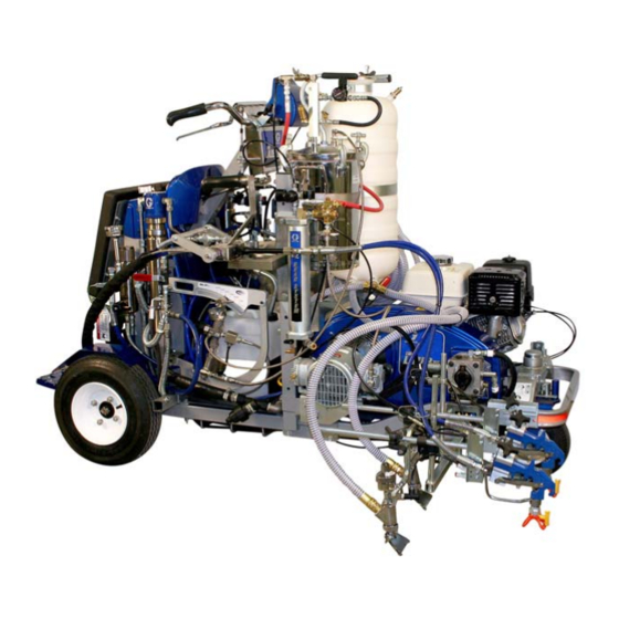
LineLazer IV 250
Self-Propelled Line Striper
For
the application of line striping materials.
For use with only Benox
For professional use only.
For outdoor use only.
Not for use in hazardous locations or explosive atmospheres.
Maximum Operating Speed: 10 mph (16 kph)
Maximum Operating Pressure: 3000 psi (20.7 MPa, 207 bar)
Model 17G589
Important Safety Instructions
Read all warnings and instructions in this manual,
related manuals and the engine manual.
Be familiar with the controls and the proper usage of
the equipment. Save these instructions.
MMA
L40LV liquid initiator BPO (B)
®
Related Manuals
LL IV 250 DC Operation
Global Symbols
LL IV 250 DC Repair
LL IV 250 DC Parts
Pressurized Bead System
Bead Gun Kit
Bead Gun
Displacement Pump
Airless Spray Gun
2-Gallon Pressure Tank
LL IV 250 DC Repair (French
LL IV 250 DC Repair (Spanish
3A3111 A
EN
333388
334224
334053
334054
332230
332226
308612
309277
308491
308370
334136
334137
Advertisement
Table of Contents

Related Manuals for Graco LineLazer IV 250MMA


Summary of Contents for Graco LineLazer IV 250MMA
- Page 1 Operation, Parts LineLazer IV 250 3A3111 A Self-Propelled Line Striper the application of line striping materials. For use with only Benox L40LV liquid initiator BPO (B) ® For professional use only. For outdoor use only. Not for use in hazardous locations or explosive atmospheres. Maximum Operating Speed: 10 mph (16 kph) Related Manuals Maximum Operating Pressure: 3000 psi (20.7 MPa, 207 bar)
-
Page 2: Table Of Contents
Notes ........25 Graco Standard Warranty ....26... - Page 3 Warnings Warnings The following warnings are for the setup, use, grounding, maintenance, and repair of this equipment. The exclama- tion point symbol alerts you to a general warning and the hazard symbols refer to procedure-specific risks. When these symbols appear in the body of this manual or on warning labels, refer back to these Warnings. Product-specific hazard symbols and warnings not covered in this section may appear throughout the body of this manual where applicable.
- Page 4 Warnings WARNING INJECTION HAZARD High-pressure fluid from gun, hose leaks, or ruptured components will pierce skin. This may look like just a cut, but it is a serious injury that can result in amputation. Get immediate surgical treatment. • Do not spray without tip guard and trigger guard installed. •...
- Page 5 Warnings WARNING MOVING PARTS HAZARD Moving parts can pinch, cut or amputate fingers and other body parts. • Keep clear of moving parts. • Do not operate equipment with protective guards or covers removed. • Do not wear loose clothing, jewelry or long hair while operating equipment. •...
-
Page 6: Important Benzoyl Peroxide (Bpo) Information
Important Benzoyl Peroxide (BPO) Information WARNING BURN HAZARD Equipment surfaces and fluid that’s heated can become very hot during operation. To avoid severe burns: • Do not touch hot fluid or equipment. PERSONAL PROTECTIVE EQUIPMENT Wear appropriate protective equipment when in the work area to help prevent serious injury, including eye injury, hearing loss, inhalation of toxic fumes, and burns. -
Page 7: Component Identification
Component Identification Component Identification Solvent Valve Mix Manifold Material Supply Valve Solvent Tank Resin Dump Valve BPO Pressure Pot Benzoylperoxide (BPO) Dump Valve Resin Tank Hydraulic Valve For complete operation and parts information refer to the related manuals listed on the cover of this document. This document provides the operation information required when spraying two part coatings. -
Page 8: Operation
Operation Operation Pressure Relief Procedure 4. Leave drain valve(s) open until you are ready to spray again. 5. If you suspect the spray tip or hose is clogged or that pressure has not been fully relieved: a. VERY SLOWLY loosen the tip guard retaining nut or the hose end coupling to relieve pressure gradually. -
Page 9: Startup
Operation Startup 2. Close material supply lever (B) on mix manifold. For additional information refer to Operation manu- al (333388). • Close solvent valve (A) on mix manifold • Close material supply lever (B) on mix manifold • Open resin dump valve (C) •... - Page 10 Operation 6. Fill tanks with resin (J), catalyst (H), and solvent (G). 7. Start the unit, see Setup/Startup in Operation man- ual (333388). 8. Verify tip and guard installation and check gun placement. See Operation manual (333388) for more information. 9.
- Page 11 Operation 11. Close resin dump valve (C). 13. Open material supply lever (B) on mix manifold. 14. Reverse tip on the spray gun. 12. Open hydraulic valve (E) to build pressure on Resin a. Engage the trigger lock. (2000-2500psi). b. Rotate tip to the spray position. ti26701a c.
- Page 12 Operation 15. Press the gun trigger button until material is clear of solvent. 16. Startup is complete. 17. Enable Ratio Assurance Monitor Alarms. See MMA Smart Control Operation, page 16. 3A3111 A...
-
Page 13: Flushing Procedure
Flushing Procedure Flushing Procedure For additional information refer to Operation manu- al (333388). • Close hydraulic valve (E) • Reverse tip on spray gun • Press the gun trigger button until pressure is gone (below 500 psi) • Close material supply lever (B) on mix manifold •... - Page 14 Flushing Procedure c. Disengage the trigger lock. 5. Check to see that you have the solvent pump on. ti26789a 3. Press the gun trigger button until pressure is gone (below 500 psi). 6. Open solvent valve (A) on mix manifold. 4.
-
Page 15: Cleanup
Cleanup Cleanup For additional information refer to Operation manu- 1. Perform the Flushing Procedure, page 13. al (333388). 2. Follow Pressure Relief Procedure, page 8. • Perform the Flushing Procedure, page 13 3. Remove spray tip and soak in solvent. •... -
Page 16: Mma Smart Control Operation
MMA Smart Control Operation MMA Smart Control Operation Menu Tree 3A3111 A... -
Page 17: Mma/Epoxy Mode
MMA Smart Control Operation MMA/Epoxy Mode 10-40 5-20 15-30 5-10 00:47 0.0’ 2500 psi 2300 psi LOW PSI PAINT 10.0’ - - - - gallons SPACE 30.0’ - - - JOB MIL ti26782a Ref. Description Ref. Description LOW PSI is flashed if either pressure is below the 1 When the GUN SHUTOFF is enabled, the guns do user defined MIN PSI VALUE. - Page 18 MMA Smart Control Operation 1. Use to select Ratio Assurance. Ref. Description 1 Open Flush Timer Menu. 2 ENABLE or DISABLE alarm notification. 3 Number of minutes before alarm is displayed. 2. Press to open Flush Timer Menu. 3. Set Flush Timer parameters. ti26785a 3A3111 A...
-
Page 19: 17H095 Mix Manifold Parts
17H095 Mix Manifold Parts 17H095 Mix Manifold Parts ti26727a 17H095 Mix Manifold Parts List Ref. Part Description Qty. Ref. Part Description Qty. 215618 VALVE, check 124859 BOLT, shoulder, 1/4-20 x 5/16 O-ring 262808 KIT, valve relief Endisys 112309 NUT, hex, jam INJECTOR, fluid 16E334 HANDLE, manifold HANDLE, grip... -
Page 20: 16P125 Slave Pump Linkage Parts
16P125 Slave Pump Linkage Parts 16P125 Slave Pump Linkage Parts ti26739a Ref. Part Description Qty. Ref. Part Description Qty. 7486-03 WASHER, flat, fender 1/4 16N776 KIT, upper link, slave 24M092 PIN, quick release, 1.5 x 0.25 16N775 KIT, lower link, slave 111040 NUT, lock, nylock, 5/16 119999 BOLT, shoulder 120476 BOLT, shoulder, 5/16... - Page 21 16P125 Slave Pump Linkage Parts 902d 902b 902f 902a 902g 902f 902e Apply pipe sealant to threads. 903a Apply thread locker to mating surfaces or threads. Apply grease to mating surfaces or threads. Torque to 240 in-lb (27.1 N•m). 903c 903b Torque to 225-275 in-lb (25.4-31.1 N•m).
-
Page 22: 17H093 Bpo Slave Pump Parts List
16P125 Slave Pump Linkage Parts 17H093 BPO Slave Pump Parts List Installation Tools (not shown): Qty. Ref. Part Description HOUSING, slave pump Foot valve seat installation tool, 16N966 24C479 KIT, cartridge, FRP Foot valve seat deluxe removal tool, 24N253 (includes 902a CARTRIDGE, slave pump foot valve seat installation tool, 16N996) -
Page 23: 17H093 Slave Pump Fittings
17H093 Slave Pump Fittings 17H093 Slave Pump Fittings Ref. Part Description Qty. Ref. Part Description Qty. 16N617 KIT, repair, catalyst, yoke 17H096 KIT, repair, drain valve 113641 GAUGE, pressure, fluid HOSE 16G410 MANIFOLD, pressure, transducer 17H093 KIT, repair, pump, slave complete HOSE 15F782 HARNESS, transducer 3A3111 A... -
Page 24: Subassembly Items
Subassembly Items Subassembly Items Ref. Part Description Qty. 236155 TANK, low pressure 16M652 TANK, solvent, assembly 241705 GUN, spray 3A3111 A... -
Page 25: Notes
Notes Notes 3A3111 A... -
Page 26: Graco Standard Warranty
With the exception of any special, extended, or limited warranty published by Graco, Graco will, for a period of twelve months from the date of sale, repair or replace any part of the equipment determined by Graco to be defective.
Need help?
Do you have a question about the LineLazer IV 250MMA and is the answer not in the manual?
Questions and answers