
Related Manuals for Emtek EMTouch


Summary of Contents for Emtek EMTouch
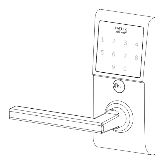
- Page 1 Installation & Programming Guide EMTouch™ Electronic Lever Locksets ASSA ABLOY, the global leader in door opening solutions...
- Page 2 What’s in the Box ITEM NO. DESCRIPTION QTY. Outside Trim Plate Assembly Adjustable Latch for 2 3/ 8 ” or 2 3/4” Backset Inside Trim Plate Assembly Inside Chassis Inside Trim Plate #8-32 x 3/ 8 " Flat Head Machine Screw 9V Alkaline Battery #8-32 x 11/2"...
- Page 3 Preparation 1. Confirm Handing HANDING OF DOOR IS ALWAYS DETERMINED FROM THE OUTSIDE In-Swing Doors Out-Swing Doors outside outside Hinge is on the right. Hinge is on the left. Hinge is on the right. Hinge is on the left. Door is Right Hand (RH). Door is Left Hand (LH).
- Page 4 How to Install 1. Install Adjustable Latch Fasten Adjustable Latch using two #8 x 3/4” Wood Screws (item #6). To remove Pin: Scan QR code for Push Plastic Latch Pin (item #9) installation video through latch with screwdriver. Plastic The Adjustable Latch is factory Latch shipped with a 23/4”...
- Page 5 3. Install Outside Trim Plate Assembly Step 1: While holding Outside Trim Plate Assembly, Press the Plastic Extender (A) into end of Spindle Shaft (B). The Shaft is properly aligned when the marking ‘TOP’ can be seen from an overhead view. THIS SIDE ON TOP.
- Page 6 4. Install Inside Chassis Step 1: Confirm the position of Cam Link. For Right Hand Locks: Turn to right position. CAM LINK MUST REMAIN IN THE CORRECT POSITION DURING INSTALLATION. For Left Hand Locks: Turn to left position. Step 2: Feed the Wire Harness through Inside Chassis.
- Page 7 Step 3: Fasten Inside Chassis using two #8-32 x 11/2” Flat Head Machine Screw (item #5). CHECK ALIGNMENT BEFORE FULLY TIGHTENING SCREWS. Step 4: Connect Wire Harness (A) and tuck Connectors as shown (B). Step 5: Install Battery. 9V Battery For optimal performance, always use a good quality battery.
- Page 8 5. Install Inside Trim Plate Fasten Inside Trim Plate using two #8-32 x 3/8” Flat Head Machine Screws (item #4c). USER CODES ARE LOCATED ON THE INSIDE TRIM PLATE & ON PAGE 11. Inside Correct position for installation.Thumbcam must be positioned as Scan QR code for installation video shown (Neutral Position)*...
- Page 9 How to Use Your Lock is Ready to Use Your Emtek lock is shipped with two 4-digit user codes and a 6-digit programming code. These codes are randomly generated at the factory. (Turn to next page for Programming Instructions.) To Unlock: 1.
- Page 10 In order to perform each of the following six functions, the lock must first be placed in Programming Mode: 1. Press and hold EMTEK button for 3 seconds 2. Yellow LED flashes, then remains solid*, number keys also illuminate 3. Enter Programming Code 4.
- Page 11 Outside Thumb Turn Enabled * If 3 consecutive incorrect codes are entered, the lock emits 4 short beeps and a flashing Red EMTEK button. The lock will not accept additional input for 20 seconds (20 beeps). When the next valid code is entered the lock will beep quickly 3 times to alert of the incorrect codes.
- Page 12 ASSA ABLOY is the global leader in door opening solutions, dedicated to satisfying end-user needs for security, safety and convenience. Copyright © 2012, Emtek Products, Inc. an ASSA ABLOY Group company. All rights reserved. Reproduction in whole or in part without the express written permission of Emtek Products, Inc. is prohibited.
Need help?
Do you have a question about the EMTouch and is the answer not in the manual?
Questions and answers