
Related Manuals for Emtek Keypad Deadbolt Locksets


Summary of Contents for Emtek Keypad Deadbolt Locksets
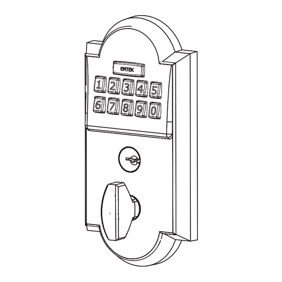
- Page 1 Installation & Programming Guide Keypad Deadbolt Locksets ASSA ABLOY, the global leader in door opening solutions...
-
Page 2: What's In The Box
What’s in the Box ITEM NO. DESCRIPTION QTY. Outside Trim Plate Assembly Deadbolt Latch Assembly 2 3/ 8 ” or 2 3/4” Backset Inside Trim Plate Assembly Inside Chassis Inside Trim Plate #8-32 x 3/ 8 ” Flat Head Machine Screw 9V Alkaline Battery - Type 6LR61 #8-32 x 11/2”... - Page 3 Preparation 1. Door Prep 2 3/8” or 2 3/4” Backset 1/8” Deep 2 1/4” 2 1/8” Diameter Bore 1 “ 1” Diameter Edge Bore 2. Door Jamb Prep Step 1: Fasten Security Plate using two #10 x 3” Wood Screws (item #9). Step 2: Fasten Strike Plate using two #8 x 3/4”...
-
Page 4: How To Install
How to Install 1. Install Latch Fasten Latch using two #8 x 3/4” Wood Screws (item #6). THE LATCH ASSEMBLY MUST BE ORIENTED AS SHOWN AND THE BOLT MUST BE IN THE RETRACTED POSITION FOR INSTALLATION. Crosshairs at bottom. 2. Remove Screws from Inside Trim Plate Use a Phillips head screwdriver to remove screws (item #4c) shown below and detach Inside Trim Plate from the Inside Chassis. - Page 5 3. Install Outside Trim Plate Assembly Position the Outside Trim Plate Assembly through the bore hole. Feed wire harness through the bore hole. ONCE POSITIONED, OUTSIDE TRIM PLATE ASSEMBLY REQUIRES SUPPORT. Flat Shaft through latch. Flat Shaft must be in vertical position for installation.
- Page 6 4. Install Inside Chassis Step 2: Feed the Wire Harness through Inside Chassis. Step 3: Fasten Inside Chassis using two #8-32 x 11/2” Flat Head Machine Screws (item #5). CHECK ALIGNMENT BEFORE FULLY TIGHTENING SCREWS.
- Page 7 Step 4: Connect Wire Harness (A) and tuck Connectors as shown (B). Step 5: Install Battery. 9V Battery For optimal performance, always use a good quality battery.
- Page 8 5. Install Inside Trim Plate Fasten Inside Trim Plate using two #8-32 x 3/8” Flat Head Machine Screws (item #4c). USER CODES ARE LOCATED ON THE INSIDE TRIM PLATE & ON PAGE 11. Inside Correct for installation Incorrect for installation *Unlocked Locked *Unlocked position is required for installation and removal of the Inside...
- Page 9 How to Use Your Lock is Ready to Use Your Emtek lock is shipped with two 4-digit user codes and one 6-digit programming code. These codes are randomly generated at the factory. (Turn to next page for Programming Instructions.) To Unlock: 1.
- Page 10 Programming Your Lock In order to perform each of the following six functions, the lock must first be placed in Programming Mode: 1. Press and hold EMTEK button for 3 seconds 2. Yellow LED flashes, then remains solid* 3. Enter Programming Code 4.
- Page 11 • 2 Green LED flashes Outside Thumb Turn Enabled * If 3 consecutive incorrect codes are entered, the lock emits 4 short beeps and a flashing Red EMTEK button. The lock will not accept additional input for 20 seconds (20 beeps).
- Page 12 ASSA ABLOY is the global leader in door opening solutions, dedicated to satisfying end-user needs for security, safety and convenience. Copyright © 2011, Emtek Products, Inc. an ASSA ABLOY Group company. All rights reserved. Reproduction in whole or in part without the express written permission of Emtek Products, Inc. is prohibited.
Need help?
Do you have a question about the Keypad Deadbolt Locksets and is the answer not in the manual?
Questions and answers