Advertisement
Installation and Assembly:
Lock Down Hardware for Display Base Stands
Model: HL4UN-002, HL4UN-002-Q10
Parts List
Description
A 1/4-20 x 1 3/4" carriage bolt
B M4 x 16 mm phillips trilobe screw
C M4 x 16 mm socket pin screw
D 1/4-20 sloped nut
M4 x 12 mm socket pin screw
E
#8 flat washer
F
G plastic cap
H 4 mm allen wrench
C
H
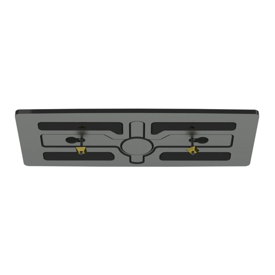
Measure distance between center lines of cut outs in
1
bottom of display base.
location of holes at point 1 and point 2, on table.
Drill two holes using a 9/32'' drill bit.
NOTE: Display and base may appear
different than illustrated
POINT 1
BOTTOM OF BASE
HL4UN-002
Qty.
Part #
2
520-1017
2
520-2621
2
520-1087
3
530-0035
520-1079
2
2
540-1001
2
590-1294
1
560-9646
D
Use measurement to mark
FRONT
MEASURE
DISTANCE
HL4UN-002-Q10
Qty.
Part #
20
520-1017
20
520-2621
20
520-1087
23
530-0035
520-1079
20
20
540-1001
20
590-1294
3
560-9646
E
Insert two 1/4-20 x 1-3/4" carriage bolts (A)
2
into bottom of display base as shown in detail 1.
A
DETAIL 1
POINT 2
1 of 2
A
F
• drill
• 9/32" drill bit
• 5/8" open box wrench
FRONT
ISSUED: 06-03-11 SHEET #:120-9110-1
B
G
TOOLS NEEDED
Advertisement
Table of Contents

Related Manuals for PEERLESS HL4UN-002


Summary of Contents for PEERLESS HL4UN-002
- Page 1 Installation and Assembly: Lock Down Hardware for Display Base Stands Model: HL4UN-002, HL4UN-002-Q10 Parts List HL4UN-002 HL4UN-002-Q10 Description Qty. Part # Qty. Part # A 1/4-20 x 1 3/4" carriage bolt 520-1017 520-1017 B M4 x 16 mm phillips trilobe screw...
- Page 2 DISPLAY SCREEN C or E DISPLAY BASE fig 4.1 fig 4.2 2 of 2 ISSUED: 06-03-11 SHEET #:120-9110-1 © 2011, Peerless Industries, Inc. All rights reserved. All other brand and product names are trademarks or registered trademarks of their respective owners.
Need help?
Do you have a question about the HL4UN-002 and is the answer not in the manual?
Questions and answers