Advertisement
Available languages
Available languages
Quick Links
Installation and Assembly:
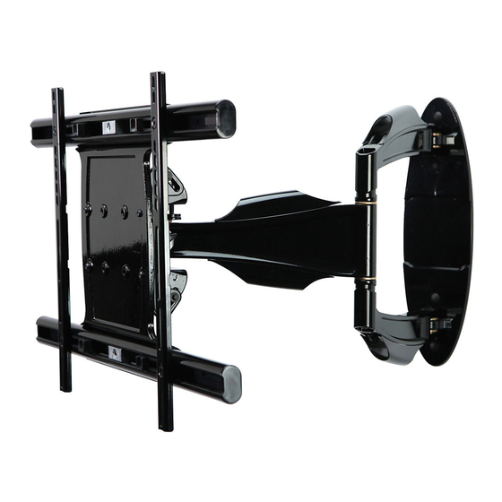
Universal Articulating Arm Wall Mount for 32" to 52" Plasma
and LCD Screens
Models: SA752PU, SA752PU-S
U L
C
US
©
Maximum UL Load Capacity: 90 lb (41 kg)
3215 W. North Ave. • Melrose Park, IL • (800) 865-2112 or (708) 865-8870 • Fax: (708) 865-2941 • www.peerlessmounts.com
ISSUED: 10-30-09 SHEET #: 095-9297-2 12-04-09
Advertisement

Related Manuals for PEERLESS SA752PU


Summary of Contents for PEERLESS SA752PU
- Page 1 Installation and Assembly: Universal Articulating Arm Wall Mount for 32" to 52" Plasma and LCD Screens Models: SA752PU, SA752PU-S © Maximum UL Load Capacity: 90 lb (41 kg) 3215 W. North Ave. • Melrose Park, IL • (800) 865-2112 or (708) 865-8870 • Fax: (708) 865-2941 • www.peerlessmounts.com...
- Page 2 Note: Read entire instruction sheet before you start installation and assembly. WARNING • Do not begin to install your Peerless product until you have read and understood the instructions and warnings contained in this Installation Sheet. If you have any questions regarding any of the instructions or warnings, for US customers please call Peerless customer care at 1-800-865-2112, for all international customers, please contact your local distributor.
- Page 3 Parts List SA752PU SA752PU-S Description Qty. Part # Part # A wall arm assembly 095-P1642 095-4642 B universal adapter bracket 095-P1635-2 095-4635-2 C wood screws 520-1202 520-2165 D concrete anchors 590-0320 590-0320 E M10 x 5 mm socket head screw...
- Page 4 Adapter Bracket Fasteners M5 x 12 mm (4) M4 x 12 mm (6) (520-1027) M6 x 12 mm (4) (504-9013) M5 x 25 mm (4) M6 x 20 mm (4) (520-1128) (520-9543) (520-9402) M6 x 25 mm (4) M4 x 25 mm (4) (520-1208) (504-1015) I.D.
- Page 5 Installation to Single Wood Stud Wall WARNING • Installer must verify that the supporting surface will safely support the combined load of the equipment and all attached hardware and components. • Tighten wood screws so that wall plate is fi rmly attached, but do not overtighten. Overtightening can damage the screws, greatly reducing their holding power.
- Page 6 WARNING • When installing Peerless wall mounts on cinder block, verify that you have a minimum of 1-3/8" (35 mm) of actual concrete thickness in the hole to be used for the concrete anchors. Do not drill into mortar joints! Be sure to mount in a solid part of the block, generally 1"...
- Page 7 WARNING • Tighten screws so screen brackets are fi rmly attached to screen. Do not tighten with excessive force. Overtightening can cause stress damage to screws, greatly reducing their holding power and possibly causing screw heads to become detached. Tighten to 40 in. • lb (4.5 N.M.) maximum torque. •...
- Page 8 SCREEN MULTI-WASHER SCREW If you have any questions, please call Peerless customer care at 1-800-865-2112. For Bump-out or Recessed Back Screen Begin with longer length screw, hand thread screw through multi-washer, screen brackets (B) and spacer in that order into screen as shown below. Screw must make at least three full turns into the mounting hole and fi t snug into place.
- Page 9 WARNING • Do not lift more weight than you can handle. Use additional man power or mechanical lifting equipment to safely handle placement of the screen. • Do not tighten screws with excessive force. Overtightening can cause damage to mount. Tighten M10 x 15 mm screws (E) to 40 in.
- Page 10 Adjustment of Flat Panel Screen WARNING • M10 x 15 mm screws (E) must be securly tightened before changing orientation of wall arm assembly (A). Failure to lock adapter bracket can cause screen to come off of mount. FOR PORTRAIT OR LANDSCAPE SCREEN ORIENTATION: Remove two M5 x 12 mm screws and rotation block from top of tilt head as shown in top view and rear view.
- Page 11 TENSIONS SCREW TENSIONS SCREWS 11 of 46 ISSUED: 10-30-09 SHEET #: 095-9297-2 12-04-09 © 2009, Peerless Industries, Inc. All rights reserved. All other brand and product names are trademarks or registered trademarks of their respective owners.
- Page 12 Instalación y montaje: Soportes de pared de brazo articulador para pantallas planas de 32" a 52" Modelos: SA752PU, SA752PU-S © Máxima capacidad de carga para UL: 90 lb (41 kg) 3215 W. North Ave. • Melrose Park, IL • (800) 865-2112 or (708) 865-8870 • Fax: (708) 865-2941 • www.peerlessmounts.com...
-
Page 13: Table Of Contents
Hoja de Instalación. Si tiene alguna pregunta acerca de cualquiera de las instrucciones o las ad- vertencias, por favor, llame a Servicio al Cliente de Peerless al 1-800-865-2112 si está en EE. UU. Si es un cliente internacional, por favor, comuníquese con su distribuidor local. -
Page 14: Lista De Piezas
Español Lista de piezas SA752PU SA752PU-S Descripción Cant. Nº de pieza Nº de pieza A brazo de pared 095-P1642 095-4642 B soporte adaptador universal 095-P1635-2 095-4635-2 C tornillos para madera 520-1202 520-2165 D concreto de anclajes 590-0320 590-0320 E tornillos de M10 x 15 mm... - Page 15 Español Fijaciones para los soportes adaptadores M5 x 12 mm (4) M4 x 12 mm (6) (520-1027) M6 x 12 mm (4) (504-9013) M5 x 25 mm (4) M6 x 20 mm (4) (520-1128) (520-9543) (520-9402) M6 x 25 mm (4) M4 x 25 mm (4) (520-1208) (504-1015)
-
Page 16: Instalación En Una Pared
Español Instalación en una pared con montante de madera único ADVERTENCIA • El instalador debe verifi car que la superfi cie de apoyo sea capaz de soportar fi rmemente la carga combinada del equipo y todos los herrajes y componentes. •... - Page 17 ADVERTENCIA • Cuando instale soportes de pared Peerless en bloques de hormigón de escorias, verifi que que tengan un mínimo de 1-3/8" (35 mm) de superfi cie efectiva de concreto en el agujero que va a utilizar para los anclajes de concreto. ¡No perfore en las juntas de mortero! Asegúrese de instalar el soporte en una parte sólida del bloque, generalmente a un mínimo de 1"...
- Page 18 Español Instalación de los soportes adaptadores ADVERTENCIA • Apriete los tornillos de tal modo que los soportes adaptadores queden fi rmemente sujetos. No apriete aplicando demasiada fuerza. El apriete excesivo puede causar daño por esfuerzo a los tornillos, reduciendo enormemente su fuerza de fi jación y causando el posible desprendimiento de sus cabezas.
- Page 19 ARANDELA MÚLTIPLE TORNILLO Si tiene alguna pregunta, por favor, llame a Servicio al Cliente de Peerless al 1-800-865-2112. Instalación de un televisor que tiene la parte posterior abultada o empotrada Comience con uno de los tornillos más largos, enrósquelo, con la mano, a través de la arandela múltiple, los soportes de la pantalla (B) y el espaciador, en ese orden, a la parte posterior de la pantalla, como se muestra abajo.
-
Page 20: Instalación Del Soporte Adaptador Universal
Español ADVERTENCIA • No levante más peso del que puede manejar. Cuente con otra persona que lo ayude o utilice un equipo mecánico de izar para levantar y colocar la pantalla con seguridad. • No apriete los tornillos con fuerza excesiva. Apretarlos en exceso puede dañar el soporte. Apriete los tornillos M10 x 15 mm (E) a un máximo de 40 pulg-lb (4.5 N•m) de par torsor. - Page 21 Ajuste de la Pantalla Plana Español ADVERTENCIA Trabar la placa de pared montaje (A) con los tornillos M10 x 15 mm (E) antes de cambiar la orientación. Puede • causar que la pantalla se desprenda de la unidad de soporte si le dan un golpe accidentalmente. PARA COLOCAR LA PANTALLA VERTICAL U HORIZONTALMENTE: Quite los dos tornillos de M5 x 12 mm y el bloque rotatorio de la parte superior del cabezal inclinable, como se muestra en la vista superior y en la vista trasera.
-
Page 22: Manejo De Los Cables
NOTA: No lo gire más de media vuelta. TORNILLOS TENSORES TORNILLOS TENSORES 22 de 46 PUBLICADO: 10-30-09 HOJA #: 095-9297-2 12-04-09 © 2009, Peerless Industries, Inc. Todos los derechos reservados. Cualesquiera otras marcas y nombres de productos son marcas comerciales o registradas de sus respectivos dueños. - Page 23 Installation et montage : Montants muraux pour écrans plats articulés pour écrans de 32 à 52 pouces Modèles: SA752PU, SA752PU-S © Capacité de charge UL maximale: 90 lb (41 kg) 3215 W. North Ave. • Melrose Park, IL • (800) 865-2112 or (708) 865-8870 • Fax: (708) 865-2941 • www.peerlessmounts.com PUBLIÉ...
- Page 24 REMARQUE: lisez entièrement la fi che d’instructions avant de commencer l’installation et l’assemblage. AVERTISSEMENT • Ne commencez pas à installer votre produit Peerless avant d’avoir lu et assimilé les instructions et les avertisse- ments contenus dans cette fi che d’installation. Pour toute question concernant les instructions ou les avertissements, veuillez appeler le service à...
- Page 25 Français Liste des pièces SA752PU SA752PU-S Description Qté Pièce nº Pièce nº A bras mural 095-P1642 095-4642 B adaptateurs universels 095-P1635-2 095-4635-2 C vis à bois 520-1202 520-2165 D concreto d’ancrage 590-0320 590-0320 E vis M10 x 15 mm 520-9262...
- Page 26 Français Fixations du support adaptateur M5 x 12 mm (4) M4 x 12 mm (6) (520-1027) M6 x 12 mm (4) (504-9013) M5 x 25 mm (4) M6 x 20 mm (4) (520-1128) (520-9543) (520-9402) M6 x 25 mm (4) M4 x 25 mm (4) (520-1208) (504-1015)
- Page 27 Français Installation sur un mur à montant en bois AVERTISSEMENT • L’installateur doit s’assurer que la surface de support pourra soutenir sans danger la charge combinée de l’équipement, de toute sa visserie et de tous ses composants. • Serrez les vis à bois de manière que la plaque murale soit fermement fi xée, mais sans excès. Un serrage excessif peut endom- mager les vis et en réduire considérablement le pouvoir de maintien.
- Page 28 AVERTISSEMENT • Si vous installez des montures murales Peerless sur un bloc de béton de mâchefer, vérifi ez que vous disposez d’une épaisseur de béton d’au moins 35 mm (1 3/8 po) dans le trou destiné aux ancrages de béton. Ne percez pas dans les joints de mortier ! Veillez à...
- Page 29 Français AVERTISSEMENT • N’employez pas une force excessive pour serrer les vis. Un serrage excessif peut endommager le support. Serrez les vis à un couple maximum de 4,5 Nm (40 po-lb). • Si les vis ne sont pas enfoncées de trois tours complets dans les inserts ou si elles sont serrées au maximum sans parvenir à fi...
- Page 30 RONDELLE UNIVERSELLE Pour toutes questions, appelez le service à la clientèle de Peerless au 1-800-865-2112. Pour les écrans à dos convexe ou concave Commencez par la vis la plus longue et vissez-la manuellement à l’écran en la faisant passer à travers la rondelle tout-usage, les supports de l'écran (B) et l’entretoise comme indiqué...
- Page 31 Français AVERTISSEMENT • Ne soulevez pas plus que votre capacité. Faites-vous aider par une autre personne ou utilisez un système de levage mécanique pour effectuer une installation de l’écran en toute sécurité. • Ne serrez pas les vis de façon excessive. Un serrage excessif peut endommager le montant. Serrez les vis M10 x 15 mm (E) à un couple maximal de 40 po-lb (4,5 N.m).
- Page 32 Réglage d’un écran plat Français AVERTISSEMENT • Si le plaque murale (A) n’est pas verrouillé avec deux vis M10 x 15 mm (E) avant que l'orientation est changée, l’écran peut se détacher du montant s’il est heurté accidentellement. ORIENTATION DE L'ÉCRAN SELON UN FORMAT VERTICAL OU HORIZONTAL : Retirez les deux vis M5 x 12 mm et le bloc de rotation de la partie supérieure de la tête basculante à...
- Page 33 33 sur 46 PUBLIÉ LE : 10-30-09 FEUILLE n : 095-9297-2 12-04-09 © 2009, Peerless Industries, Inc. Tous droits réservés. Tous les autres noms de marques et de produits sont des marques de commerce ou déposées de leurs propriétaires respectifs.
- Page 34 Anbringung und Zusammenbau: Gelenkarm-Wandhalter für Flachbildschirme von 32 - 52 Zoll Modelle: SA752PU, SA752PU-S © Maximale UL Tragfähigkeit: 90 lb (41 kg) 3215 W. North Ave. • Melrose Park, IL • (800) 865-2112 or (708) 865-8870 • Fax: (708) 865-2941 • www.peerlessmounts.com...
- Page 35 HINWEIS: Lesen Sie die gesamte Anleitung, bevor Sie mit der Anbringung und dem Zusammenbau beginnen. ACHTUNG • Beginnen Sie mit der Anbringung Ihres Peerless-Produkts erst, nachdem Sie die in dieser Montageanleitung enthaltenen Anleitungen und Achtungshinweise gelesen und sich gründlich mit ihnen vertraut gemacht haben. Falls Sie Fragen hinsichtlich irgendeiner der Anleitungen oder Achtungshinweise haben, wenden Sie sich in den USA bitte an den Peerless-Kundendienst unter der Rufnummer 1-800-865-2112.
- Page 36 Deutsch Teileliste SA752PU SA752PU-S Beschreibung Anz. Teile Nr. Teile Nr. A Wandarm 095-P1642 095-4642 B Universell-Adapterhalterung 095-P1635-2 095-4635-2 C Holzschrauben 520-1202 520-2165 D Beton Dübel 590-0320 590-0320 E M10 x 15 mm Schrauben 520-9262 520-9534 F Befestigungsteilabdeckungen 590-1324 590-4324 G Kabelbinder...
- Page 37 Deutsch BEFESTIGUNGSTEILE FÜR ADAPTERHALTERUNG M5 x 12 mm (4) M4 x 12 mm (6) (520-1027) M6 x 12 mm (4) (504-9013) M5 x 25 mm (4) M6 x 20 mm (4) (520-1128) (520-9543) (520-9402) M6 x 25 mm (4) M4 x 25 mm (4) (520-1208) (504-1015) I.D.
- Page 38 Deutsch Anbringung an Wänden mit einer Holzständerreihe ACHTUNG • Bei der Anbringung muss darauf geachtet werden, dass die Wand die kombinierte Last von Bildschirm und allen Befestigungsteilen und -komponenten tragen kann. • Ziehen Sie die Schrauben fest genug an, dass die Wandplatte sicher befestigt ist, doch ohne sie zu überdrehen. Durch Überdrehen können die Schrauben beschädigt werden, wodurch ihr Haltevermögen stark reduziert wird.
- Page 39 Deutsch ACHTUNG • Bei der Anbringung von Peerless-Wandhaltern an Porenbetonstein muss sichergestellt werden, dass die tatsächliche Stärke des Betons, in den das Loch für die Betondübel gebohrt wird, mindestens 35 mm (1 3/8 Zoll) beträgt. Bohren Sie nicht in Mörtelfugen! Achten Sie darauf, dass die Anbringung an einem massiven Teil des Blocks erfolgt, im Allgemeinen mindestens 25 mm (1 Zoll) von der Blockseite entfernt.
- Page 40 Deutsch ACHTUNG • Ziehen Sie die Schrauben nicht zu fest an. Durch Überdrehen kann der Halter beschädigt werden. Das maximale Drehmoment zum Festziehen der Schrauben darf 40 in • lb (4,5 Nm) nicht überschreiten. • Sind die Schrauben nicht um drei volle Umdrehungen in die Löcher des Bildschirms eingeschraubt oder stoßen sie unten an und die Halterung ist noch immer nicht sicher befestigt, kann der Bildschirm beschädigt werden oder das Produkt kann versagen.
- Page 41 BILDSCHIRM MEHRLOCHSCHEIBE SCHRAUBE Wenden Sie sich mit Fragen an den Peerless-Kundendienst unter der Telefonnummer +1-800-865-2112 (innerhalb der USA). Bildschirme mit Wölbung oder Vertiefung an der Rückseite Beginnen Sie mit der längeren Schraube und schrauben Sie diese wie nachstehend dargestellt von Hand durch die Mehrlochscheibe, die Bildschirmhalterungen (B) und den Abstandhalter (in dieser Reihenfolge) in den Bildschirm.
- Page 42 Deutsch ACHTUNG • Ziehen Sie immer eine zusätzliche Person heran oder verwenden Sie mechanische Hebegeräte, um den F lachbildschirm sicher zu heben und zu positionieren. • Ziehen Sie die Schrauben nicht zu fest an. Durch Überdrehen kann der Halter beschädigt werden. Das maximale Drehmoment zum Festziehen der M10 x 15 mm Schrauben (E) darf 40 in •...
- Page 43 Einstellung des Flachbildschirms Deutsch ACHTUNG Adapterplatte (A) • Wenn der nicht mit M10 x 15 mm Schrauben ( ) gesichert und arretiert wird, kann der Bildschirm bei versehentlichem Anstoßen vom Halter herabfallen. AUSRICHTEN DES BILDSCHIRMS IM HOCH- ODER QUERFORMAT: Entfernen Sie mithilfe des 5 mm Inbusschlüssels (I) zwei M5 x 12 mm Schrauben und den Drehblock von der Oberseite des Neigungskopfs wie in der Draufsicht und Rückansicht dargestellt.
- Page 44 HINWEIS: Drehen Sie die Schraube um nicht mehr als eine halbe Umdrehung. SPANNUNGS-SCHRAUBE SPANNUNGS-SCHRAUBE 44 von 46 AUSGEGEBEN: 10-30-09 BLATT NR.: 095-9297-2 12-04-09 © 2009, Peerless Industries, Inc. Alle Rechte vorbehalten. Alle anderen Marken- und Produktnamen sind eingetragene Marken der jeweiligen Eigentümer.
- Page 45 Limited Five-Year Warranty. This warranty does not cover damage caused by (a) service or repairs by the customer or a person who is not authorized for such service or repairs by Peerless Industries, Inc., (b) the failure to utilize proper packing when returning the product, (c) incorrect installation or the failure to follow Peerless’ instructions or warnings when installing, using or storing the product, or (d) misuse or accident, in transit or otherwise, including in cases of third party actions and force majeure.
- Page 46 Peerless ne saura en aucun cas être tenue pour responsable de tout préjudice accidentel ou induit, ou de tout préjudice dû au vol d’un produit, qu’il soit ou non protégé...
Need help?
Do you have a question about the SA752PU and is the answer not in the manual?
Questions and answers