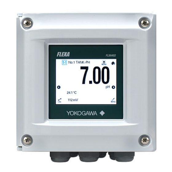
YOKOGAWA FLXA402 Technical Information
4-wire converter, modbus communication
Hide thumbs
Also See for FLXA402:
- User manual (93 pages) ,
- Installation and wiring (43 pages) ,
- Technical information (37 pages)
Table of Contents
Advertisement
Quick Links
Technical
Information
TI 12A01F01-62EN
CONTENTS
1.
General .................................................................................................... 2
1.1
1.2
1.3
1.4
1.5
1.6
1.7
2.
MODBUS map ......................................................................................... 6
2.1
2.2
2.3
2.4
3.
Alarm .....................................................................................................31
3.1
3.2
3.3
3.4
3.5
Revision Information .....................................................................................38
FLEXA, FLXA, SENCOM and FieldMate are trademarks or registered trademarks of Yokogawa Electric Corporation.
All other company and product names mentioned in this document are trademarks or registered trademarks of their respective companies.
FLXA402 4-Wire Converter
MODBUS Communication
MODBUS setup ..................................................................................................2
MODBUS master................................................................................................3
Function code/Exception code ........................................................................3
MODBUS communication ................................................................................4
MODBUS password ..........................................................................................5
How to change SENCOM SA address .............................................................5
Connection .........................................................................................................5
COIL: Coil register .............................................................................................7
INPUT_REGISTER: Input Register ..................................................................8
2.2.1
Status..................................................................................................................9
2.2.2
mA Output, mA Input, Contact Output, Contact Input ..................................... 10
2.2.3
HART ............................................................................................................... 10
2.2.4
Script .................................................................................................................11
2.2.5
Converter Alarm ...............................................................................................11
2.2.6
Sensor measured value .................................................................................. 12
HOLD_REGISTER............................................................................................14
2.3.1
Error setting (0- ) .............................................................................................. 14
2.3.2
mA input settings (1700-) ................................................................................ 18
2.3.3
Contact input settings (1800-) ......................................................................... 18
2.3.4
mA output settings (1000-) .............................................................................. 19
2.3.5
Contact output settings (1500-) ....................................................................... 21
2.3.6
Display settings (3000-) ................................................................................... 22
2.3.7
Display settings Script (3500-) ....................................................................... 24
2.3.8
Display settings Trend (3300-)....................................................................... 25
2.3.9
Display settings Others (3400-) ..................................................................... 26
2.3.10
Advanced settings MODBUS setting (2100-) ................................................ 26
2.3.11
Advanced settings HART setting (2000-) ...................................................... 27
2.3.12
Advanced settings Ethernet setting (2200-) .................................................. 28
2.3.13
Advanced settings Others setting (4000-) ..................................................... 28
2.3.14
MODBUS native (4200-) ................................................................................. 28
Identification ....................................................................................................29
Alarm list (Converter) ......................................................................................32
Alarm list (pH) ..................................................................................................34
Alarm list (SC) ..................................................................................................35
Alarm list (ISC) .................................................................................................36
Alarm list (DO)..................................................................................................37
Yokogawa Electric Corporation
2-9-32, Nakacho, Musashino-shi, Tokyo, 180-8750 Japan
TI 12A01F01-62EN
©Copyright Nov. 2018
1st Edition Nov. 2018
2nd Edition Apr. 2019
Advertisement
Table of Contents

Related Manuals for YOKOGAWA FLXA402


Summary of Contents for YOKOGAWA FLXA402
-
Page 1: Table Of Contents
Alarm list (DO)....................37 Revision Information ..................38 FLEXA, FLXA, SENCOM and FieldMate are trademarks or registered trademarks of Yokogawa Electric Corporation. All other company and product names mentioned in this document are trademarks or registered trademarks of their respective companies. Yokogawa Electric Corporation... -
Page 2: General
MODBUS Communication This document describes MODBUS communication by the FLXA402 4-Wire Converter. Before communicating using the MODBUS protocol, refer to the User’s Manual of the FLXA402 4-Wire Converter (IM 12A01F031-03EN Operation of converter) for details of the parameters. For latest User’s Manual, download it from our website or scan QR code. -
Page 3: Modbus Master
• wide panel operation, larger than FLXA402 Data memory YOKOGAWA GX series with RS485 MODBUS are recommended for process data saving. MODBUS communication enables to store larger amount of process data than FLXA402 mA output. Function code/Exception code MODBUS Function code used for FLXA402... -
Page 4: Modbus Communication
(Error code 03) is replied. NOTE When FLXA402 has access to measured data, you cannot set devices by using HMI or other devices on the network. Even after FLXA402 loses access, this situation remains unchanged for 3 seconds. -
Page 5: Modbus Password
SENCOM SA sensor, you have to connect the SENCOM SA one by one and change the address. SENCOM SA refers to SA11, some sensors connected to SA11. SA11 is used when -S5 (SENCOM SA) is specified for FLXA402 1st/2nd input. Connection Ethernet On the FLXA402 network, Ethernet MODBUS allows 2 sessions. -
Page 6: Modbus Map
MODBUS Communication MODBUS map Data type for FLXA402 MODBUS map Data type Definition float floating point (4byte) IEEE754 NaN: 0x7FFFFFFF int16 16 bit signed integer uint16 16 bit unsigned integer uint32 32 bit unsigned integer ASCII character set (using one byte per... -
Page 7: Coil: Coil Register
MODBUS Communication COIL: Coil register address item name Value/description Reserved all 0 Do not change. WRITE_STATUS Read only Shows access authority. WRITE_FLAG Gains access authority. Turn ON this coil bit when modifying the setting by Modbus protocol CONVERTER_RESTART Restarts the converter SQUAWK_SWITCH Starts backlight flashing. -
Page 8: Input_Register: Input Register
MODBUS Communication INPUT_REGISTER: Input Register MODBUS address are assigned to parameters of the converter status including AO and HART. Address from 1000 to 1999 are for the measured value obtained from sensors. Address Name Comment 0 to 999 Converter Status on Converter, AO, HART. See 2.2.1 through 2.2.5. -
Page 9: Status
MODBUS Communication 2.2.1 Status address item name Type Value/description converter status uint32 MODBUS status of the converter (bit fields) changes at Housing HR setting changes at Housing IR renewed 8-29 Reserved Ethernet link up. ON at cable connection Bluetooth link up, “ON” when Bluetooth is connected. converter alarm uint32 Integrated information on alarms of the converter or connected sensors. -
Page 10: Ma Output, Ma Input, Contact Output, Contact Input
MODBUS Communication address item name Type Value/description WASH/HOLD uint16 WASH/HOLD status status HOLD: ON: HOLD (bit fields) WASH: slave bitON: being washed, Master bitON: Wash recovering Reserved mA1_HOLD mA2_HOLD mA3_HOLD mA4_HOLD 8, 9 S1_WASH 10, 11 S2_WASH 12, 13 S3_WASH 14, 15 Reserved 2.2.2 mA Output, mA Input, Contact Output, Contact Input... -
Page 11: Script
MODBUS Communication 2.2.4 Script Latest revision does not support script, or arithmetic by multiple sensors. address item name Type ** Value/description 43,44 SCRIPT_DIFFERENTIAL_PH float differential (pH) * 45,46 SCRIPT_DIFFERENTIAL_ORP float differential (ORP) * 47,48 SCRIPT_DIFFERENTIAL_CON- float differential (CONDUCT) * DUCT 49,50 SCRIPT_DIFFERENTIAL_RESIST float... -
Page 12: Sensor Measured Value
MODBUS Communication 2.2.6 Sensor measured value address item name Type Value/description ushort device_failure (bit enum) ushort sensor_failure (bit enum) See the table of alarms for bit assignment. ushort meas_warning (bit enum) ushort device_status (bit enum) 4, 5 temp_measure float Temperature pH_measure float ORP_measure... - Page 13 MODBUS Communication address item name Type Value/description ushort device_failure (bit enum) ushort sensor_failure (bit enum) See the table of alarms for bit assignment. ushort meas_warning (bit enum) ushort device_status (bit enum) temp_measure float Temperature SC1_measure float Conductivity 1 SC2_measure float Conductivity 2 10,11 concentration1...
-
Page 14: Hold_Register
MODBUS Communication HOLD_REGISTER 2.3.1 Error setting (0- ) For further information, see section 4.7 “Error settings” in the User’s Manual IM 12A01F01-03EN Operation of Converter. Error settings See Chapter 3 for bit assignment. Register (by bit) 4 alarm types : Measurement alarm, I/O alarm, Maintenance status, Setting error, according to NE107 : Failure (F), Function check (S), Out of specification (C), Maintenance required (M), and (Off), (N). - Page 15 MODBUS Communication Error settings-sensor Address NE107 Address NE107 Address NE107 Address NE107 Name Type PH Device fail uint16 (bit Sensor status fields) Measure alarm Device status SC Device fail Sensor status Measure alarm Device status ISC Device fail Sensor status Measure alarm Device status DO Device fail...
- Page 16 MODBUS Communication Sensor error simulation (mode) Connection Connection Connection Connection Address Address Address Address Name Type number number number number PH Device fail uint16 (bit Sensor status fields) Measure alarm Device status SC Device fail Sensor status Measure alarm Device status ISC Device fail Sensor status Measure alarm...
- Page 17 MODBUS Communication Sensor error simulation Connection Connection Connection Connection Address Address Address Address Name Type number number number number PH Device fail uint16 (bit Sensor status fields) Measure alarm Device status SC Device fail Sensor status Measure alarm Device status ISC Device fail Sensor status Measure alarm...
-
Page 18: Ma Input Settings (1700-)
MODBUS Communication 2.3.2 mA input settings (1700-) Address Parameter Type Description 1700 Type int16 None(0), Current(1), Temperature(2), Pressure(3) 1701, 1702 Temperature float -40~260 1703, 1704 20mA float -40~260 1705, 1706 Pressure float 0.0~999.9 1707, 1708 20mA float 0.0~999.9 1709, 1710 Damping time float 0~3600... -
Page 19: Ma Output Settings (1000-)
MODBUS Communication 2.3.4 mA output settings (1000-) Address Parameter Type Description mA3(Ad) mA4(Ad) mA#: # refers to 1 to 4. 1000 1105 1210 1315 int16 Output(0), Simulate(1), Off(2) 1001 1106 1211 1316 Process int16 pH(0), Temperature(1), ORP(2), rH(3), (output) parameter Conductivity-TC1(4), Conductivity- TC2(5), Resistivity-TC1(6), Resistivity- TC2(7), Concentration-TC1(8),... - Page 20 MODBUS Communication 21point- mA Output value *1 Type Position Value Position Value Position Value point 1. 1021, 1022 1063, 1064 1126, 1127 1168, 1169 float point 2. 1023, 1024 1065, 1066 1128, 1129 1170, 1171 point 3. 1025, 1026 1067, 1068 1130, 1131 1172, 1173 point 4.
-
Page 21: Contact Output Settings (1500-)
MODBUS Communication 2.3.5 Contact output settings (1500-) Address Parameter Type Description S1 (R) S2 (R) S3 (R) S4 (R) S#: # refers to 1-4 1500 1550 1600 ― int16 Off(0), Alarm(1), Hold(2), Wash(3), Fail(4), USP(5), Simulate(6) ― ― ― 1650 Alarm(0), Fail(1), Simulate(2), Fail safe(3) 1501 1551... -
Page 22: Display Settings (3000-)
MODBUS Communication 2.3.6 Display settings (3000-) Address Parameter Type Description Display Display Display Display 3000 ― ― ― Process int16 Sensor1-1(1), Sensor1-2(2), Sensor1-3(3), parameter slot Sensor1-4(4), Sensor2-1(5), Sensor2-2(6), Sensor2-3(7), Sensor2-4(8), Converter(9) ― 3031 3062 3093 None(0), Sensor1-1(1), Sensor1-2(2), Sensor1-3(3), Sensor1-4(4), Sensor2-1(5), Sensor2-2(6), Sensor2-3(7), Sensor2-4(8), Converter(9) 3001... - Page 23 MODBUS Communication Address Parameter Type Description Display Display Display Display 3124 3155 3186 3217 Process int16 None(0), Sensor1-1(1), Sensor1-2(2), parameter slot Sensor1-3(3), Sensor1-4(4), Sensor2-1(5), Sensor2-2(6), Sensor2-3(7), Sensor2-4(8), Converter(9) 3125 3156 3187 3218 1st line int16 Empty(0), pH(1), Temperature(2), ORP(3), rH(4), Conductivity-TC1(5), Conductivity- 3126 3157 3188...
-
Page 24: Display Settings Script (3500-)
MODBUS Communication 2.3.7 Display settings Script (3500-) Latest revision does not support script or arithmetic by multiple sensors. Address Parameter Type Description 3500-3503 Script unit strings 1 ASCII Script arithmetic, text lines on HMI display 3504-3507 Script unit strings 2 HMI Script characters* 3508-3511 Script unit strings 3... -
Page 25: Display Settings Trend (3300-)
MODBUS Communication 2.3.8 Display settings Trend (3300-) Address Parameter Type Description Trend Trend Trend Trend 3300 ― ― ― Process int16 pH(1), Temperature(2), ORP(3), rH(4), Conductivity- parameter TC1(5), Conductivity-TC2(6), Resistivity-TC1(7), Resistivity-TC2(8), Concentration-TC1(9), Concentration-TC2(10), Oxygen(11), Differential pH(12), Differential ORP(13), Differential CONDUCT(14), Differential RESIST(15), Differential DO(16), Average pH(17), Average ORP(18), Average CONDUCT(19), Average RESIST(20), Average DO(21), Ratio(22), Passage(%)(23), Rejection(%) -
Page 26: Display Settings Others (3400-)
MODBUS Communication 2.3.9 Display settings Others (3400-) Address Parameter Type Description 3400 Auto Return int16 Disable(0), 10 min.(1), 60 min.(2) 3401 Luminance int16 10%(0), 20%(1), 30%(2), 40%(3), 50%(4), 60%(5), 70%(6), 80%(7), 90%(8), 100%(9) 3402 Backlight saver int16 Disable(0), 10 min.(1), 30 min.(2), 60 min. 3403 MONITOR Display int16... -
Page 27: Advanced Settings Hart Setting (2000-)
MODBUS Communication 2.3.11 Advanced settings HART setting (2000-) Address Parameter Type Description 2000 Network int16 0~63 address 2001 Loop Current int16 Disable(0), Enable(1) Mode 2002 int16 AO1 current(0), AI(1), Differential pH(2), Differential OPR(3), Differential CONDUCT(4), Differential RESIST(5), Differential DO(6), Average 2003 int16 pH(7), Average OPR(8), Average CONDUCT(9),... -
Page 28: Advanced Settings Ethernet Setting (2200-)
2201, 2202 IP Address uint32 2203, 2204 Subnet mask uint32 2205, 2206 Default gateway uint32 CAUTION Ethernet setting is reflected onto the system, after FLXA402 reboots. 2.3.13 Advanced settings Others setting (4000-) Address Parameter Type Description 4000 Temperature int16 °C(0), °F(1) -
Page 29: Identification
MODBUS Communication 2.4 Identification object object name Type Value/description 0x00 vendor_name ASCII YOKOGAWA 0x01 product_code FLXA402 0x02 major_minor_version create from software revision (e.g. 01-01.01) object object name Type Value/description 0x03 vendor_url ASCII space(64) 0x04 product_name space(16) 0x05 model_name space(8) 0x06... - Page 30 MODBUS Communication Hardware structure Name Description Bluetooth yes/no 0b: yes, 1b: no 1, 2 digital network type 00b: none, 01b: Modbus RTU(RS485), 10b: Modbus TCP/IP sensor type of 000b: none, 001b: SENCOM SA, 010b: digital sensor, 011b: Sensor1 analog sensor sensor type of 000b: none, 001b: SENCOM SA, 010b: digital sensor, 011b: Sensor2...
-
Page 31: Alarm
MODBUS Communication Alarm For further information on "Error settings" see 4.7 in the User's Manual IM 12A01F03-01EN Alarm numbers start with XY as shown below. Address CH1-1 Housing Address CH1-2 Address CH1-3 Address CH1-4 Address CH2-1 Address CH2-2 Address CH2-3 Address CH2-4 TI 12A01F01-62EN Apr. -
Page 32: Alarm List (Converter)
MODBUS Communication Alarm list (Converter) Alarm Alarm name Alarm default*1 Note Number Hardware failure 0001 Internal com. erro 0002 IO mod. param. read error 0003 Com. mod. param. read err 0004 CPU param. read error 0005 VGB calc. error 0010 Ratio calc. - Page 33 MODBUS Communication Alarm Alarm name Alarm default*1 Note Number mA configuration error 1 0090 mA configuration error 2 0091 mA configuration error 3 0092 mA configuration error 4 0093 Error in mA table 1 0094 Error in mA table 2 0095 Error in mA table 3 0096...
-
Page 34: Alarm List (Ph)
MODBUS Communication Alarm list (pH) Alarm Alarm name Alarm default*1 Note Number EEPROM error XY00 User param. read error XY01 Err on: Factory param. Error XY02 Sensor mod. not working XY03 ID chip data param. read err XY05 Temp. resistance too high XY4F Temp. -
Page 35: Alarm List (Sc)
MODBUS Communication Alarm list (SC) Alarm Alarm name Alarm default*1 Note Number EEPROM error XY00 User param. read error XY01 Err on: Factory param. Error XY02 Sensor mod. not working XY03 ID chip data param. read err XY05 Temp. resistance too high XY4F Temp. -
Page 36: Alarm List (Isc)
MODBUS Communication Alarm list (ISC) Alarm Alarm name Alarm default*1 Note Number EEPROM error XY00 User param. read error XY01 Err on: Factory param. Error XY02 Sensor mod. not working XY03 ID chip data param. read err XY05 Temp. resistance too high XY4F Temp. -
Page 37: Alarm List (Do)
MODBUS Communication Alarm list (DO) Alarm Alarm name Alarm default*1 Note Number EEPROM error XY00 User param. read error XY01 Err on: Factory param. Error XY02 Sensor mod. not working XY03 ID chip data param. read err XY05 Temp. resistance too high XY4F Temp. -
Page 38: Revision Information
Revision Information ● Title : FLXA402 4-Wire Converter MODBUS Communication ● Manual No. : TI 12A01F01-62EN Apr. 2019/2nd Edition Corrected (pages 31, 34 to 37) Nov. 2018/1st Edition Newly published Yokogawa Electric Corporation 2-9-32 Nakacho, Musashino-shi, Tokyo 180-8750, JAPAN http://www.yokogawa.com/ TI 12A01F01-62EN Apr. 19, 2019-00...
Need help?
Do you have a question about the FLXA402 and is the answer not in the manual?
Questions and answers